a3369b.pdf - 第30页
Control Unit MDC VTK - TR -BA- 171e - 1 - User Manua l MDS 3080 -V 21 4.2 Front Side Fig . 1: Front S ide 1 Mount ing hole 2 LC display 3 Keyp ad with 12 soft keys 4 Con trol lam p for First Drop (“func tion ”) “red” 5 C…
Control Unit MDC
20
VTK-TR-BA-171e-1 - User Manual MDS 3080-V
4 Control Unit MDC
This chapter contains relevant information about the control unit. It describes the menu
structure, keypad and functions of the control unit.
4.1 Technical Data
Value
Dimensions
128 mm H x 102 mm W x 173 mm D (w/o Kabel)
(see dimensional drawing, Page 166)
3 RU x 20 HP
Weight
ca. 1500 g
Supply Voltage
110/230 V AC/DC
Supply Frequency
50/60 Hz
Current Consumption
Max. 900 mA
During start-up, this value can increase by a factor
of 5 (start-up peak).
Recommended fuse: 16 A for 240 V resp. 110 V
Ambient Temperature
10 °C - 50 °C
Air Humidity
The relative humidity rH might not surpass 80% at
31 °C or 50% at 50 °C (connect linearly for other
temperatures).
Casing Type
Plug-in case for 19“ rack
Color of Casing
Black
Ventilation
Convection
Internal Storage Locations:
10
Display Lines
2 lines with 16 characters each
Display Color
White with background lighting
Keypad
12 softkeys
Color of Keys
Blue, beige
Control Lamps (Front)
1x Heating circuit (red)
1x First Drop (“function”, red)
1x Adjust OK (green)
1x Adjust not OK (red)
Control Lamps (Back)
1x Illuminated power lamp
Plug Contacts (Back)
1x Mains plug (110/240 V AC)
1x 9 pin Sub-D RS-232C
1x 15 pin Sub-D PLC
1x AUX-socket 24V
1x Sensor socket
1x Actuator socket
1x Socket for heating
1x Thermocouple socket
Control Unit MDC
VTK-TR-BA-171e-1 - User Manual MDS 3080-V
21
4.2 Front Side
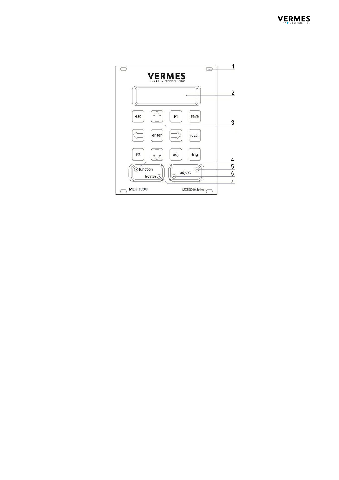
Fig. 1: Front Side
1 Mounting hole
2 LC display
3 Keypad with 12 soft keys
4 Control lamp for First Drop
(“function”) “red”
5 Control lamp for adjust “green“
6 Control lamp for adjust „red“
7 Control lamp for status of
heating „red“
LC display:
Data, service intervals and menu options are shown in the two lines of the illuminated LC display
(LCD = “liquid crystal display”). The current menu option appears in the upper line. The lower line
contains the current parameter value for dispensing, according to numerical data to be modified.
Keypad with 12 softkeys:
Menu options to control the system are selected by means of these keys.
Details for changing parameters etc. are explained in a following chapter (see paragraph 4.4,
page 25).
Control lamp for First Drop (“function”):
This red LED indicates, if there is a problem during the first drop adjust. It is also ON during the
start-up of the MDC, while the power supply unit is initialized.
Control lamps for adjust (“green” and “red”):
During the adjust, these two control lamps indicates the adjust result that is internally monitored:
• Green: the adjust value is OK. Press [Enter]-key to confirm it.
• Red: the adjust value is too high. You have to lower it according to the instructions of this
manual (see paragraph 6.5 "The Adjust Process", page 52).

Control Unit MDC
22
VTK-TR-BA-171e-1 - User Manual MDS 3080-V
You can de-/activate the control lamps for adjust. It makes no difference during the adjust (as
above). But it affects the lamps outside of the adjust (as below).
Outside of the adjust: (if the control lamps for adjust are activated)
• Red: the MDC detects an error.
• Green: the valve detects that the adjust value falls inside the adjust range.
Outside of the adjust: (if the control lamps for adjust are deactivated)
• Red: the MDC detects an error (except for an adjust error).
• The green adjust-LED stays OFF.
To de-/activate the control lamps for adjust, enter the service code 1100 (see paragraph 4.5.6
"Submenu “Service-Option”", page 33). Alternatively, you can use the serial command
SETADJLED:OFF/ON (see paragraph 8.1.2.2 "Explanations", page 88).
Control lamp for status of heating:
This red LED indicates the activity of the heating.
Heating activated – LED ON
Heating deactivated – LED OFF
Heat-up phase – LED flashes