a3369b.pdf - 第42页
C ontrol Unit MDC VTK - TR -BA- 171e - 1 - User Manua l MDS 3080 -V 33 4.5.6 Submenu “ S erv ice - Opti on ” This menu ha s two secti ons. In “Servi ce Code” , you can enter a servi ce code. If you en ter 2030 , you swi …
Control Unit MDC
32
VTK-TR-BA-171e-1 - User Manual MDS 3080-V
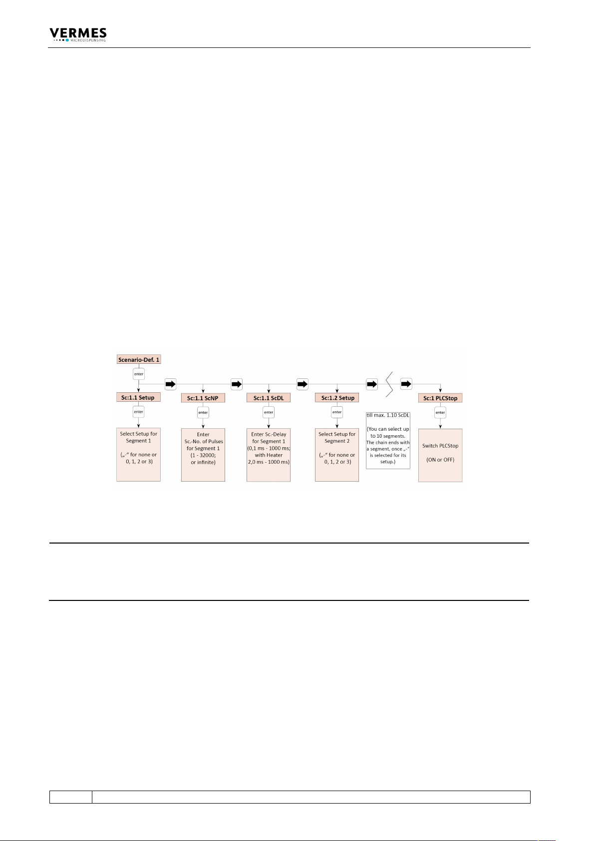
In “Sc:1.1 Setup” you can enter “0”, “1”, “2” or “3” to select a setup or “-”, to decide that no further
segment will follow. “0” is the working configuration, “1” to “3” are the parameters of the
respective setups 1 to 3. Then the scenario will end with this segment and the menu will stop
here as well. (If you later change the “-” to the number of a setup, the following segment will be
unlocked again in the menu.) If you set the blank directly in the first segment, the system will
simply use the working configuration instead of the scenario.
After entering a setup and [→], you can select the Number of Pulses next. This NP replaces the
one from the setup, which would be otherwise used. Another [→] gives the option to enter a
scenario delay. Standard value is 10 ms. Just as with the normal delay, with a heater connected to
the system the minimum scenario delay increases from 0.1 ms to 2.0 ms.
Another [→] brings you to the second segment in your scenario (“Sc:1.2 Setup”), where you have
the same options as with the first. All in all, you can combine up to ten segments (though only
four different setups, since only setups 0 to 3 are available), each with its own NP and scenario
delay, unless you stop your scenario beforehand by selecting “-” instead of a setup. After the last
segment, another [→] brings you the option to set the PLC-Stop “ON” or “OFF”. With “ON” a
scenario always ends automatically, once the trigger signal drops to “low”. No further segments
of the scenario will be performed. With the PLC-Stop “OFF”, the trigger signal only matters, if the
NP in a setup is set as “infinite”. With these parameters will be dispensed until the trigger signal
drops to “low”. If the trigger signal is already “low” when reaching the signal, only one pulse will
be shot. Then the next segment of the scenario will follow after the scenario delay (unless, of
course, it was already the last segment of the scenario).
Fig. 9: Submenu “Scenario-Def. 1”
INFORMATION
Finding PLC-Stop quickly
If you just want to change the PLC-Stop setting, but not any of the segments in your scenario, it is
quickest to use [←] once after entering the scenario, since this submenu is wrap-around, just like
all other.
Control Unit MDC
VTK-TR-BA-171e-1 - User Manual MDS 3080-V
33
4.5.6 Submenu “Service-Option”
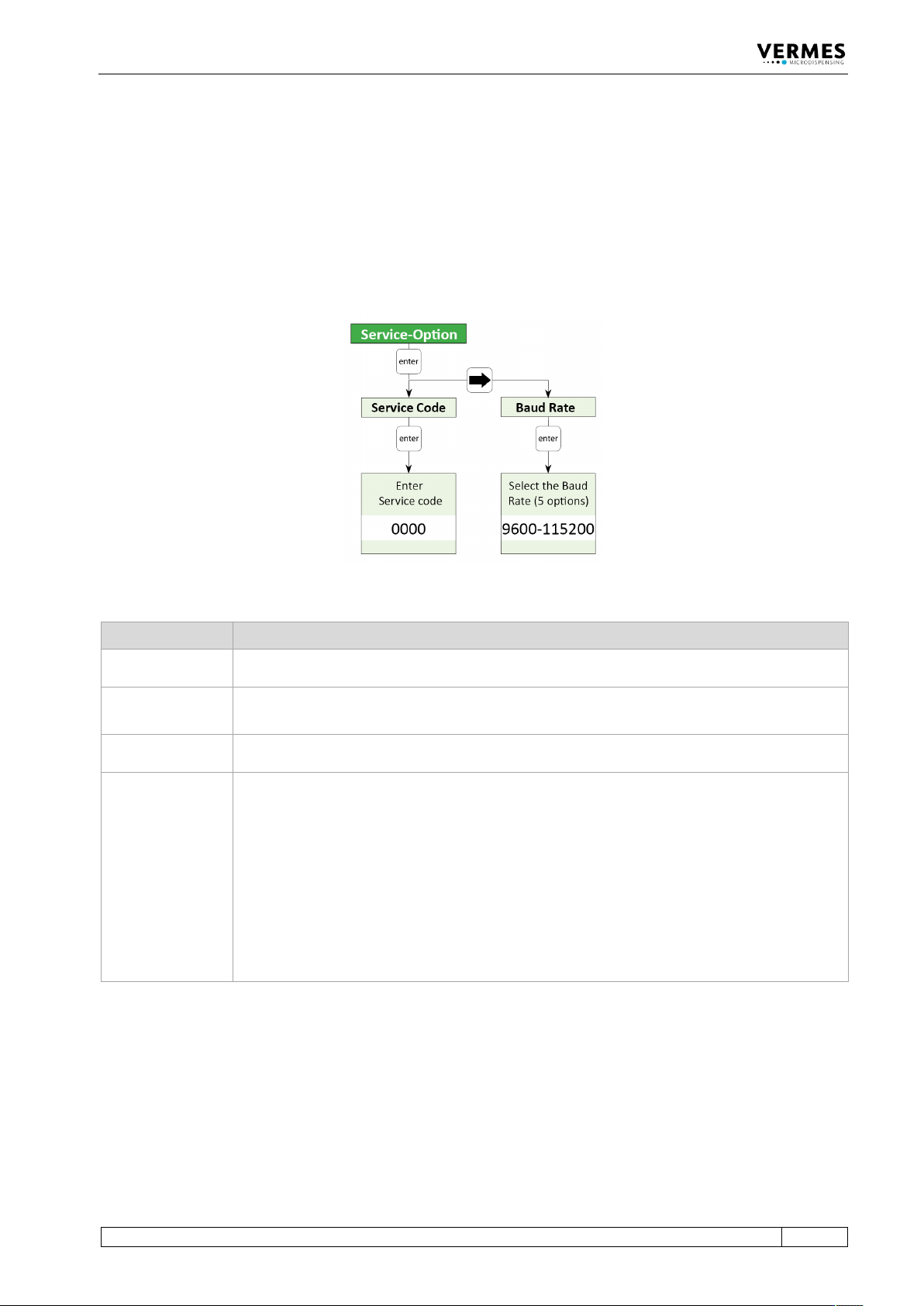
This menu has two sections. In “Service Code”, you can enter a service code. If you enter 2030,
you switch ON/OFF the valve check during start-up of the MDC. If you enter 1100, you can switch
ON/OFF the control lamps for adjust (see paragraph 4.2 "Front Side", page 21). If you enter 1000,
you enter a further submenu containing the options listed in the table below.
“Baud Rate” is used to change the baud rate. There are five possible values: 9600, 19200, 38400,
57600 and 115200 (new MDCs are set to 9600).
Fig. 10: Submenu „Service-Option“
Option Explanation
SingleDosOK
You can select between the possibilities that the SingleDosOK signal is switched per pulse or
per setup. (For the pin configuration of the PLC inter-face, see paragraph 8.2.1, page 119.)
DosOK with
Delay
You can select, if before switching the signal DosOK there should be one delay executed at
the end.
Auxiliary Mode
Here the auxiliary mode can be switched ON or OFF (see paragraph 7.13 "Auxiliary Mode",
page 76).
Factory Settings
Here any parameters can be returned to the default factory settings (see paragraph 7.10
"Factory Settings", page 69). You have got four alternatives:
• Setup 0 – 3 (the parameters of the working configuration and the setups 1 to 3 are
returned to the factory settings)
• Reset ALL (all parameters are returned, including the settings of the scenarios; also the
heater will be turned OFF and the temperature set to 1°C)
• Scenario (the parameters and settings of the scenarios are returned to the factory
settings)
• Setup ALL (the parameters of the working configuration and all setups are returned,
setups 4 – 10 receive values of setup 0)

Control Unit MDC
34
VTK-TR-BA-171e-1 - User Manual MDS 3080-V
4.6 Memories of the MDC
The MDC contains several memories to save parameter setups.
The first one is the RAM (Random Access Memory). Here the parameters of the current dispense
process will be saved. This memory will be erased when the controller is switched of or
disconnected from power. When starting again, the MDC will load the first of eleven parameter
memory sets saved on the EEPROM (Electrically Erasable Programmable Read Only Memory) into
the RAM. This first parameter setup is also called the “EEPROM current working parameter
configuration”, or short “working configuration” or “EEPROM working configuration”.
The parameter set in the EEPROM working configuration is usually the same as the parameter set
saved in the RAM memory. When using the keypad to program the controller, the two memories
will always have the same contents. The only way to create a difference in the parameter set
saved in the RAM and in the EEPROM working configuration is by using some special commands
through the RS-232C.
The remaining ten EEPROM memory sets can be used to save different parameter setups when
programming the controller through the keypad interface (use the command [Save]).
In order to change the values saved in the EEPROM working configuration you may use the MDC
keypad (enter the parameters in the menu “Pulse Parameters”, then press [Enter]).
Alternatively, you may use one of the following commands via RS-232C:
• TRIGGER:SET:<Rising>,<Open Time>,<Falling>,<Needle Lift>,<Number of Pulses>,<Delay>,1
• TRIGGER:ASET:<Rising>,<Open Time>,<Falling>,<Needle Lift>,<Number of Pulses>,<Delay>,1
• STRIGGER:SET:<Rising>,<Open Time>,<Falling>,<Needle Lift>,<Number of Pulses>,<Delay>,1
• STRIGGER:ASET:<Rising>,<Open Time>,<Falling>,<Needle Lift>,<Number of Pulses>,<Delay>,1
All values transmitted to the control unit by one of the following four commands will not be
saved in the EEPROM working configuration.
• TRIGGER:SET:<Rising>,<Open Time>,<Falling>,<Needle Lift>,<Number of Pulses>,<Delay>
• TRIGGER:ASET:<Rising>,<Open Time>,<Falling>,<Needle Lift>,<Number of Pulses>,<Delay>
• STRIGGER:SET:<Rising>,<Open Time>,<Falling>,<Needle Lift>,<Number of Pulses>,<Delay>
• STRIGGER:ASET:<Rising>,<Open Time>,<Falling>,<Needle Lift>,<Number of Pulses>,<Delay>
Instead, it will remain in the RAM memory until erased by another RS-232C command, or when
the control unit is switched OFF and the EEPROM is read out into the RAM during restart. The
reason for having these two different types of commands (the distinction is the “1” at the end) is
that it takes up to 1 sec to save the parameter set in the EEPROM.
On top of the working configuration and the ten parameter setups, there is another parameter
setting saved in the software on the EEPROM. This is called the “factory setting”. You cannot
change it. It may be loaded to the working configuration and the RAM memory after major
disturbances of the system.
Additionally, there is the possibility to save combinations of setups, so called “Scenarios” (see
paragraph 7.9 "Scenarios", page 66).