a3369b.pdf - 第60页
Initial Operation VTK - TR -BA- 171e - 1 - User Manua l MDS 3080 -V 51 6.4 Va lve s with Air co oling If you wa nt t o air cool your va lve wit h compressed ai r, you h ave to c onnect the ai r hoses t o the compr essed …
Initial Operation
50
VTK-TR-BA-171e-1 - User Manual MDS 3080-V
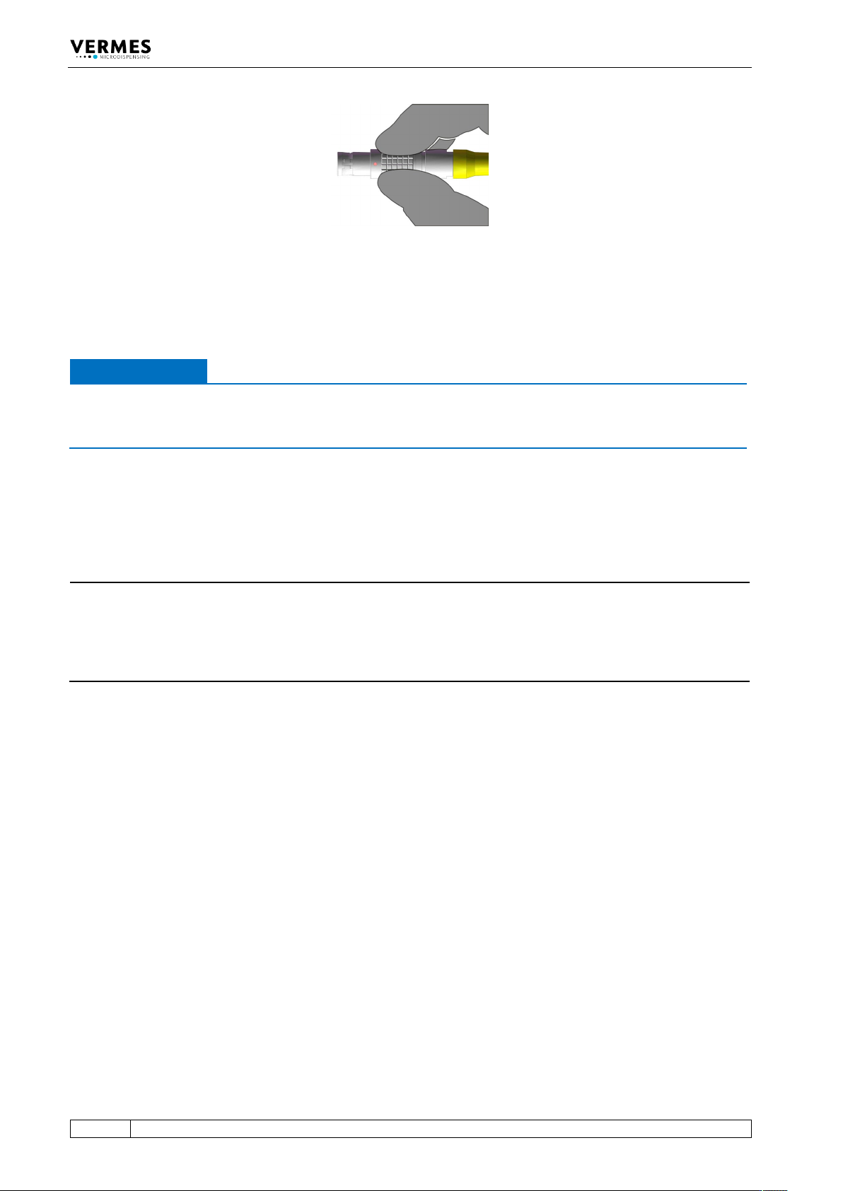
Fig. 21: Connector sensor cable - grip
6.3.3.3 Mains Cable
Power to the control unit is supplied by the black mains cable.
IMPORTANT NOTE
Type plate
Do not connect the system to the mains, before having checked the type plate of the model you
want to install (mains voltage, 110 V AC or 230 V AC).
– Step 1: Plug the cable into the socket at the bottom of the rear side of the control unit.
– Step 2: Connect the cable to the power supply.
– Step 3: Press the ON/OFF button, located on the rear side of the control unit.
INFORMATION
Valve not connected
If the valve is not connected, an error message (“199 Valve Error – Escape for Auxi.“) appears on
the screen. Switch OFF the system, disconnect it from the mains and complete the installation
before continuing. Alternatively, you can press the [ESC]-key. When confirming it with [Enter],
you change into the Auxiliary Mode (see paragraph 7.13, page 76).
Initial Operation
VTK-TR-BA-171e-1 - User Manual MDS 3080-V
51
6.4 Valves with Air cooling
If you want to air cool your valve with compressed air, you have to connect the air hoses to the
compressed air supply after finishing the cable connections of the valve. Use hoses with an inner
diameter of 4 mm.
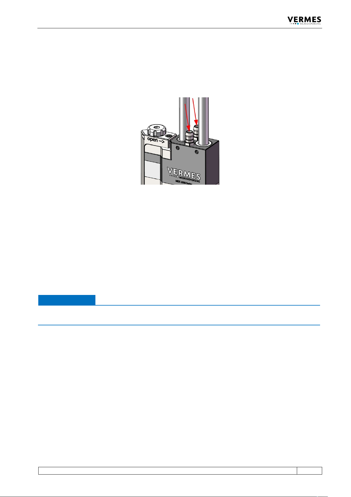
Abb. 22: Valve with air-cooling adapters
The air-cooling adapters are equal. Therefore, it does not matter which one you use as inlet, and
which one as outlet. Push end of the hose onto the air inlet of the valve you chose. Connect the
other end of the hose to the air supply.
The second connector represents the outlet, evacuating the heated compressed air from the
valve. Push one end of the hose onto the connector. When running the hose away from the
valve, take care not to impair functions of the system, or to disturb operators during their work.
For air-cooling, you should use a compressed-air pressure of about 2 bar. For a high temperature
application, you should set the pressure higher, at up to 4 bar.
IMPORTANT NOTE
Quality of compressed air
Quality of compressed air should comply with DIN ISO 8573-1.
The pneumatic supply used for cooling of the valve should be free of fine dust and condensate
and correspond to classes 1, 4, 2 according to DIN/ISO 8573-1.
• Solid particles: max. particle number/m³: 0.1 – 0.5 µm: < 20000, 0.5 – 1 µm: < 400, 1 – 5 µm: <
10 = Quality class 1
• Water content: max. pressure dew point +3°C = Quality class 4
• Residual oil: max. 0.1mg/m³ = Quality class 2
Initial Operation
52
VTK-TR-BA-171e-1 - User Manual MDS 3080-V
6.5 The Adjust Process
This chapter explains the adjust, which for a valve of the MDV 308x series is a top adjust. The
adjust is necessary for all valves. A thoroughly performed adjust is the basis for clear and
reproducible dispensing results.
This paragraph describes the normal adjust. You can also control the adjust via the serial
interface as remote adjust (see paragraph 8.2.3 "Remote Adjust", page 123).
The microdispensing system is unable to perform a regular repeatable process, if the nozzle
insert is not properly positioned relatively to the tappet prior to dispensing. Therefore, you have
to perform the adjust during initial operation and after each exchange of the nozzle unit. This is
especially important to avoid any leakage during dispensing.
IMPORTANT NOTE
Cleaning before adjust
The system has to be cleaned thoroughly before the adjust. The presence of dirt particles
jammed between the tappet surface and the nozzle insert would compromise the results.
Especially the O-ring-N around the tappet guidance has to be free of grease and dirt (for
information regarding the cleaning see paragraph 9, page 129).
IMPORTANT NOTE
Heating and adjust
In case your application uses a nozzle heater, you have to activate the heater before you start the
adjust. Make sure to wait long enough for the heater to reach stable temperature, since the
adjust could lead to an incorrect result otherwise.
Wear heat-resistant gloves while working with the valve!
INFORMATION
Abort and end of procedure, fixed adjust mode
• The adjust can be aborted at almost any time by pressing [esc]. The exception is when the
green adjust LED is ON.
• In fixed adjust mode (see paragraph 7.12, page 76) the range for the adjust is different (0 – 50
µm instead of 0 – 4 µm).
• The range, where the green adjust LED is ON, has for technical reasons a minimum size of
5.8 µm. This range can be expanded by using the serial command
“ADJUST:TO:CHANGE:<range>” (see paragraph 14.8 "Changing the Adjust Range", page 174).
This change is only recommended for selected applications in the fixed adjust mode. You
should contact our technical support first, since sometimes widening the adjust range can
lead to leakage despite a successful adjust.
Picture Explanation