00198783-01_AI_Kit_TwinVHF_Gantry_SXV3_de_en.pdf - 第107页
3 Fitting the gantry 3.1 Preparations at the Machine Assembly Instructions / Montageanleitung SIPLACE SX1/SX2 V3 Reconfiguration Kit Twin VHF mit Portal Reconfiguration Kit Twin VHF with Gantry 06/2020 107 3 Fitting the …
2 Brief Description
2.4 Tools and Equipment Required
106 Assembly Instructions / Montageanleitung SIPLACE SX1/SX2 V3 Reconfiguration Kit Twin VHF mit Portal
Reconfiguration Kit Twin VHF with Gantry 06/2020
2.4 Tools and Equipment Required
●
Gantry lift
WARNING
Installation
The installation can be performed manually, although we do recommend using a gantry lift
for safety purposes.
●
Gantry carrier plate for SX1/SX2 [03012160-xx]
●
Torque wrench (2–25Nm) [00376625‑xx]
●
Loctite 241 [02101037-xx]
●
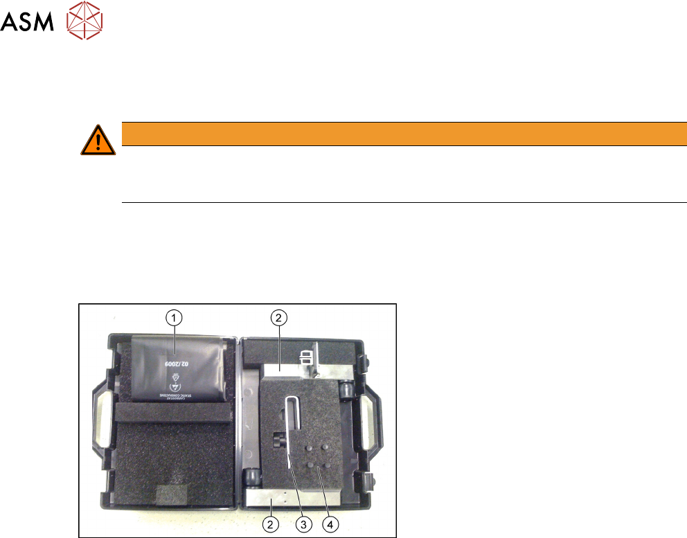
Prepared case (plastic case with foam insert) containing the following:
Prepared case
The case is configured differently depending
on the machine type.
1. Trailing cable protective foil
2. Buffer stop (2x)
3. Trailing cable mount
4. Pneumatic hose plug (4x)
●
Help of second person, if needed
●
If required, assembly instructions "Gantry modularity - SIPLACE SX1/SX2" [00196626-xx]
●
Torque screwdriver 100-500 Ncm [03078400-xx]
●
Extension/straight TX20 [03073256-xx]
●
Extension/straight [03043440-xx]
●
Bit holder for Torque Vario-S screwdriver [03078706-xx]
●
Calibration tool version 3 [03010565-xx]
3 Fitting the gantry
3.1 Preparations at the Machine
Assembly Instructions / Montageanleitung SIPLACE SX1/SX2 V3 Reconfiguration Kit Twin VHF mit Portal
Reconfiguration Kit Twin VHF with Gantry 06/2020
107
3 Fitting the gantry
NOTICE
Exemplary description
This manual describes the upgrading of gantry 2 at location 2. The assembly of gantry 1 is
the same. The diagrams sometimes show standard gantries as an example. You should
still perform the tasks described. Any differences will be explicitly indicated.
NOTICE
Mapping
When upgrading gantry 1 (master gantry) at location 1, component board mapping must be
performed after the assembly.
► Observe the technical information "Information about mapping" [DE:TI2017‑10D04]
[EN:TI2017‑10E04].
3.1 Preparations at the Machine
3.1.1 Fitting the Stationary Camera
If not already present, you will need to fit a stationary camera.
► Refer to the appropriate assembly instructions:
– Assembly instructions "SIPLACE X-Series S, SX-Series V3 stationary camera type 25/33
(GigE)" [DEEN:00197710‑xx]
3.1.2 Removing the Gantry
► If you need to remove an existing gantry before installation, read the assembly instructions
"Gantry modularity SX1/SX2 V3" [00198705-xx] (English/German).
3.1.3 Opening the Covers
► Switch off the machine, disconnect it from the power supply and secure it to prevent
unauthorized reactivation.
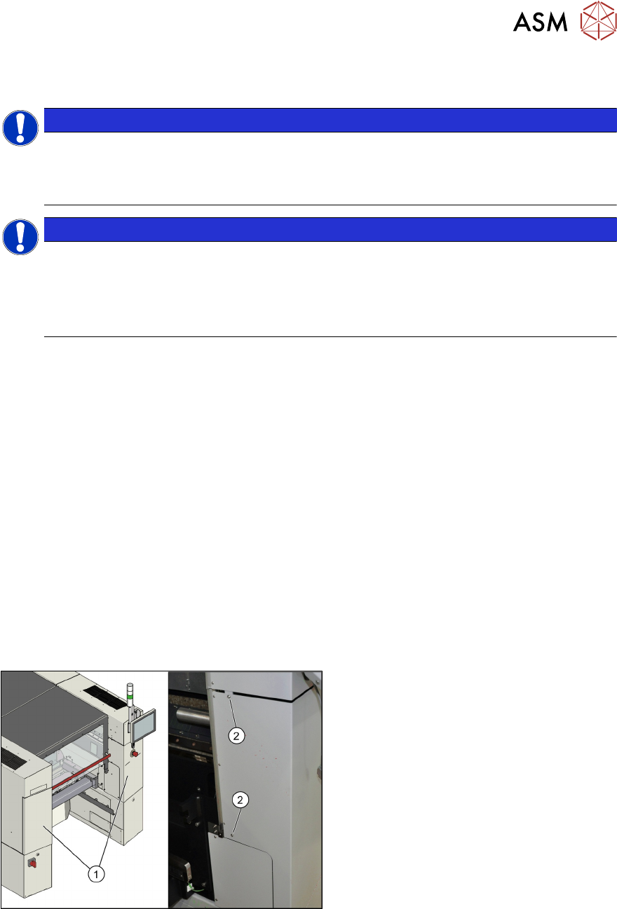
1.2 "Preparatory work..." [}85]
Fig.20: Overview of protective cover
► Open the protective cover at location 2
and move the component trolley out of
the machine.
► Loosen the two screws (2) fastening
the side covers (1)
on the right and left.
► Open the two covers (1).
3 Fitting the gantry
3.1 Preparations at the Machine
108 Assembly Instructions / Montageanleitung SIPLACE SX1/SX2 V3 Reconfiguration Kit Twin VHF mit Portal
Reconfiguration Kit Twin VHF with Gantry 06/2020
3.1.4 Removing the End Position Buffer
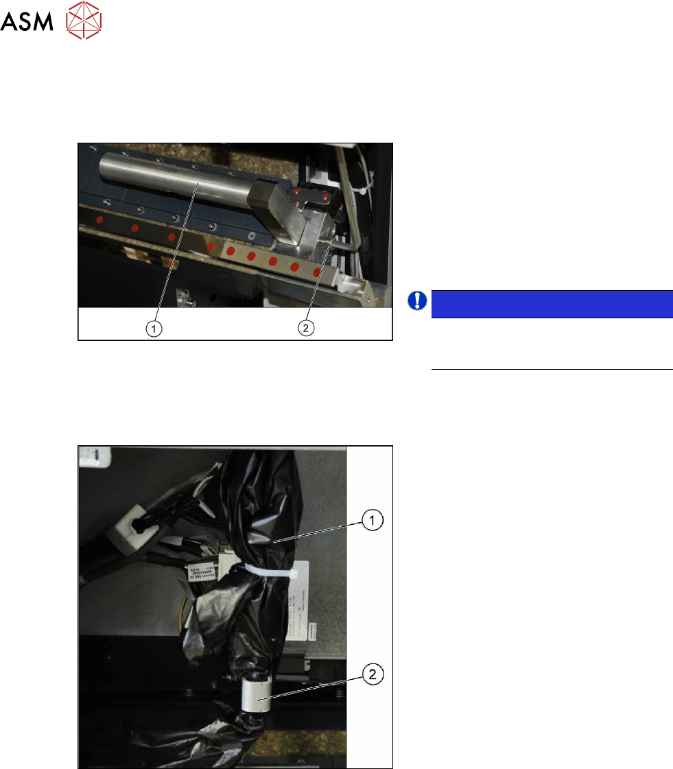
The long end position buffers must be fitted in SIPLACE SX1 machines with one gantry. When con-
verting a SIPLACE SX1 to an SX2, you need to remove this and replace it with short end position
buffers.
Fig.21: Long end position buffer
Remove the two long end position buffers.
After fitting the second gantry, fit the two
short end position buffers in place of the
long ones.
► Loosen the fastening screw (2) on the
long end position buffer (1)
.
► Remove the two end position buffers
from the right and left sides.
NOTICE!
Keep the two long end position buffers
in the "Prepared" case for fitting back
into place later on.
.
3.1.5 Preparing the Trailing Cable
Overview
Fig.22: Trailing cable, packed
The trailing cable (1) is packed in black
plastic foil and fixed to a holder(2)
.