00198783-01_AI_Kit_TwinVHF_Gantry_SXV3_de_en.pdf - 第149页
5 Appendix 5.1 Excerpts from the Service Manual Assembly Instructions / Montageanleitung SIPLACE SX1/SX2 V3 Reconfiguration Kit Twin VHF mit Portal Reconfiguration Kit Twin VHF with Gantry 06/2020 149 5.1.3 Overview of M…
5 Appendix
5.1 Excerpts from the Service Manual
148 Assembly Instructions / Montageanleitung SIPLACE SX1/SX2 V3 Reconfiguration Kit Twin VHF mit Portal
Reconfiguration Kit Twin VHF with Gantry 06/2020
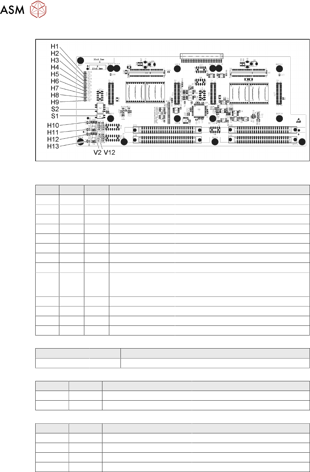
5.1.2.1 Base adapter Twin and Twin VHF
Fig.88: Base adapter Twin [03055517-04]
LED [03055517-04]
LED Color Status Signal name Description
H1 GN ON (M)HCU1 programming connector connected
H2 GN ON (M)HCU2 programming connector connected
H3 RD ON FPGA_TEST_6 1.5VDC PowerFail
H4 RD ON FPGA_TEST_2 3.3VDC PowerFail
H5 RD ON FPGA_TEST_4 5VDC PowerFail
H6 RD ON FPGA_TEST_1 15VDC PowerFail
H7 RD ON FPGA_TEST_3 DP PowerFail, not used
H8 RD ON FPGA_TEST_5 24VDC PowerFail
H9 RD ON POWERFAIL_LOCAL PowerFail board:
ON, when 1.5VDC, 3.3VDC, 5VDC and 15VDC
are outside the permissible tolerance
H10 RD ON +V_DISP_HCU1 (M)HCU1 errors
H11 GN ON +V_DISP_HCU1 (M)HCU1 OK
H12 RD ON +V_DISP_HCU2 (M)HCU2 errors
H13 GN ON +V_DISP_HCU2 (M)HCU2 OK
7-segment display V12 (M)HCU1, V2 (M)HCU2 [03055517-04]
Display Status Description
Decimal point Flashing (M)HCU1 OK
DIP switch S1 [03055517-04]
Switch Status Signal name Description
S1.1 - - Not used
S1.2 OFF RESET_HCU2 ON: Reset (M)HCU2
DIP switch S2 [03055517-04]
Switch Status Signal name Description
S2.1 OFF HCU_CM_FPGA_IO_0 „S0“ (gantry coding), not used
S2.2 OFF HCU_CM_FPGA_IO_1 „S1“ (gantry coding), not used
S2.3 OFF RESET_HCU1 ON: Reset (M)HCU!
S2.4 OFF COM_BOOT_HCU ON: Set boot mode
5 Appendix
5.1 Excerpts from the Service Manual
Assembly Instructions / Montageanleitung SIPLACE SX1/SX2 V3 Reconfiguration Kit Twin VHF mit Portal
Reconfiguration Kit Twin VHF with Gantry 06/2020
149
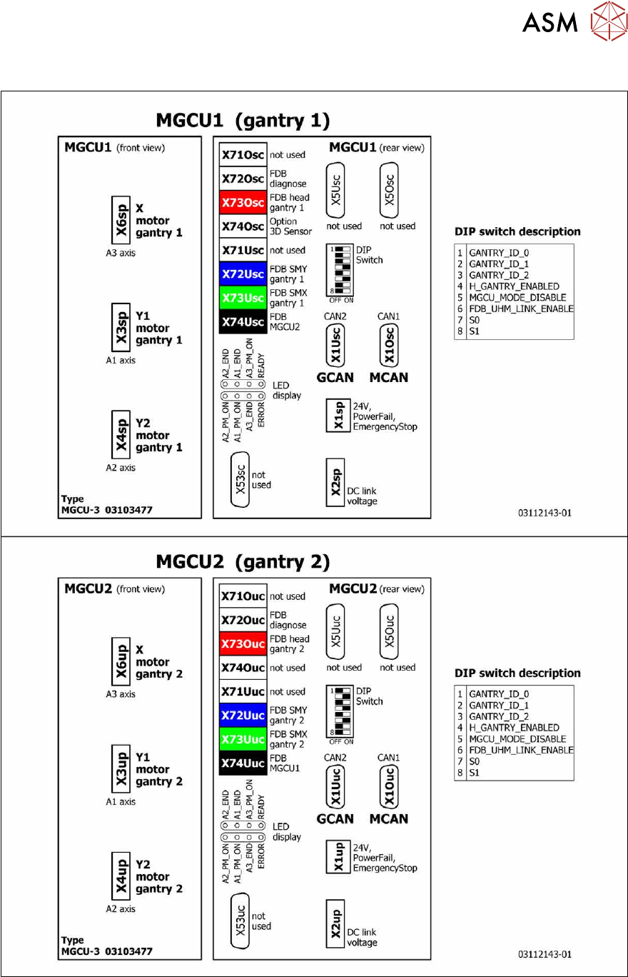
5.1.3 Overview of MGCU (Rxxxx)
Fig.89: Overview of MGCU

5 Appendix
5.2 Circuit Diagrams
150 Assembly Instructions / Montageanleitung SIPLACE SX1/SX2 V3 Reconfiguration Kit Twin VHF mit Portal
Reconfiguration Kit Twin VHF with Gantry 06/2020
5.2 Circuit Diagrams
For more information, refer to the circuit diagrams folder:
●
Detailed circuit diagrams folder for SIPLACE SX1/SX2V3 (fromRxxxx)
[DEEN:00198680‑xx]