00198783-01_AI_Kit_TwinVHF_Gantry_SXV3_de_en.pdf - 第148页
5 Appendix 5.1 Excerpts from the Service Manual 148 Assembly Instructions / Montageanleitung SIPLACE SX1/SX2 V3 Reconfiguration Kit Twin VHF mit Portal Reconfiguration Kit Twin VHF with Gantry 06/2020 5.1.2.1 Base adapte…
5 Appendix
5.1 Excerpts from the Service Manual
Assembly Instructions / Montageanleitung SIPLACE SX1/SX2 V3 Reconfiguration Kit Twin VHF mit Portal
Reconfiguration Kit Twin VHF with Gantry 06/2020
147
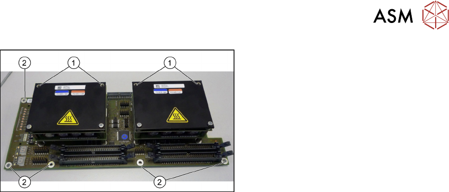
Fig.87: Head adapter MHCU (the TwinHead version shown here)
► Remove the two front screws (1)
fastening the MHCU in each case.
Make sure that you do not lose the
shims. Make a note of the number of
washers used for each screw, as this
may well differ.
► Remove all screws(2) fastening the
board and then remove the board.
► If you have ordered the base adapter without MHCU(s) you will have to convert the MHCU(s).
Remove the two screws fastening the MHCU on the underside of the board and carefully pull
the MHCU off the base adapter. Make sure not to damage the pins located below. Repeat this
procedure for the second MHCU, if necessary (for TwinHead only).
Installation
Follow the removal instructions in reverse order for installation. Also observe the following instruc-
tions:
► Checking the embedded software and performing a download if needed (see LINK).
4.2.1 "eSW Download (SW 70x)" [}142]
5 Appendix
5.1 Excerpts from the Service Manual
148 Assembly Instructions / Montageanleitung SIPLACE SX1/SX2 V3 Reconfiguration Kit Twin VHF mit Portal
Reconfiguration Kit Twin VHF with Gantry 06/2020
5.1.2.1 Base adapter Twin and Twin VHF
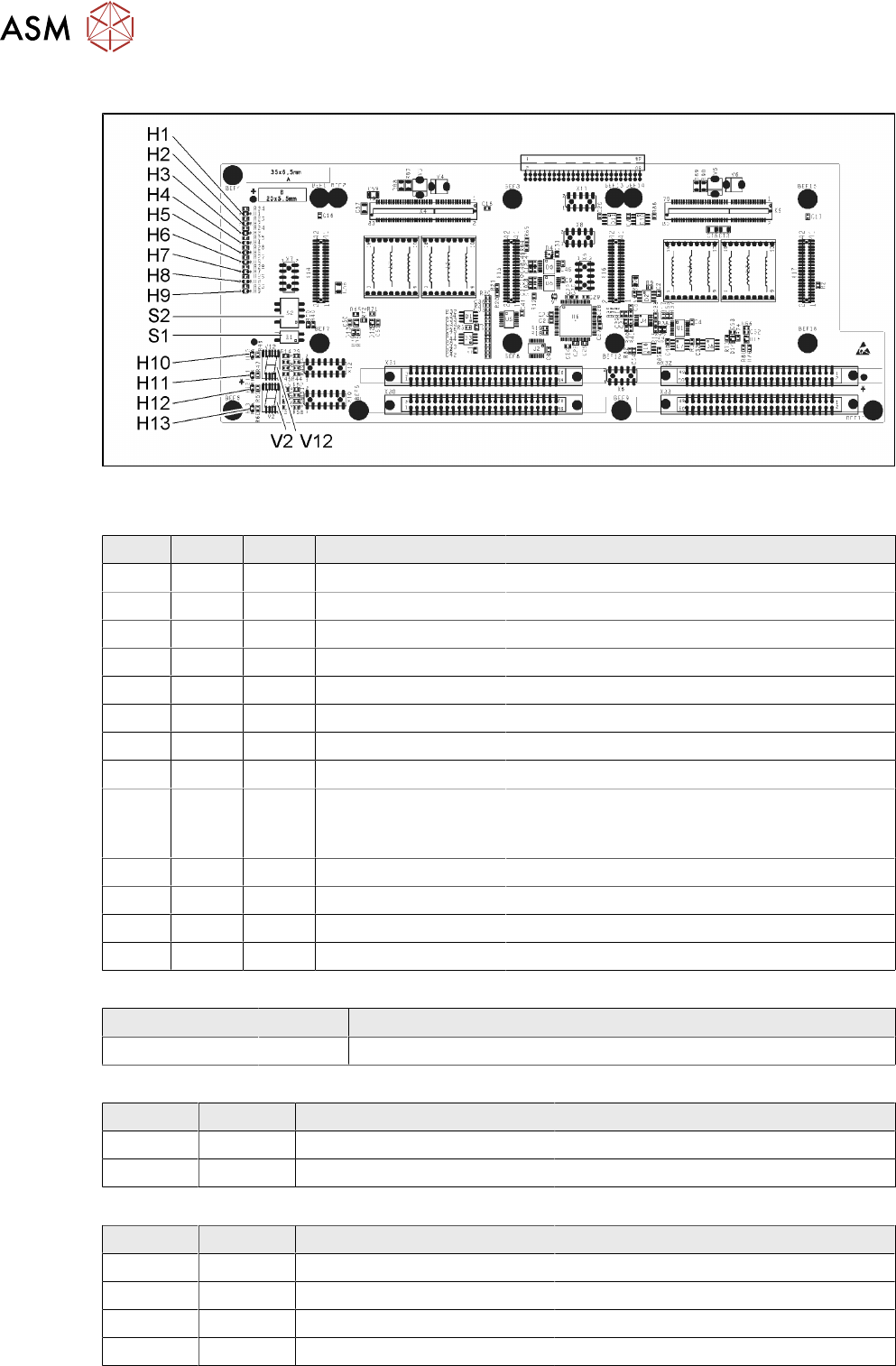
Fig.88: Base adapter Twin [03055517-04]
LED [03055517-04]
LED Color Status Signal name Description
H1 GN ON (M)HCU1 programming connector connected
H2 GN ON (M)HCU2 programming connector connected
H3 RD ON FPGA_TEST_6 1.5VDC PowerFail
H4 RD ON FPGA_TEST_2 3.3VDC PowerFail
H5 RD ON FPGA_TEST_4 5VDC PowerFail
H6 RD ON FPGA_TEST_1 15VDC PowerFail
H7 RD ON FPGA_TEST_3 DP PowerFail, not used
H8 RD ON FPGA_TEST_5 24VDC PowerFail
H9 RD ON POWERFAIL_LOCAL PowerFail board:
ON, when 1.5VDC, 3.3VDC, 5VDC and 15VDC
are outside the permissible tolerance
H10 RD ON +V_DISP_HCU1 (M)HCU1 errors
H11 GN ON +V_DISP_HCU1 (M)HCU1 OK
H12 RD ON +V_DISP_HCU2 (M)HCU2 errors
H13 GN ON +V_DISP_HCU2 (M)HCU2 OK
7-segment display V12 (M)HCU1, V2 (M)HCU2 [03055517-04]
Display Status Description
Decimal point Flashing (M)HCU1 OK
DIP switch S1 [03055517-04]
Switch Status Signal name Description
S1.1 - - Not used
S1.2 OFF RESET_HCU2 ON: Reset (M)HCU2
DIP switch S2 [03055517-04]
Switch Status Signal name Description
S2.1 OFF HCU_CM_FPGA_IO_0 „S0“ (gantry coding), not used
S2.2 OFF HCU_CM_FPGA_IO_1 „S1“ (gantry coding), not used
S2.3 OFF RESET_HCU1 ON: Reset (M)HCU!
S2.4 OFF COM_BOOT_HCU ON: Set boot mode
5 Appendix
5.1 Excerpts from the Service Manual
Assembly Instructions / Montageanleitung SIPLACE SX1/SX2 V3 Reconfiguration Kit Twin VHF mit Portal
Reconfiguration Kit Twin VHF with Gantry 06/2020
149
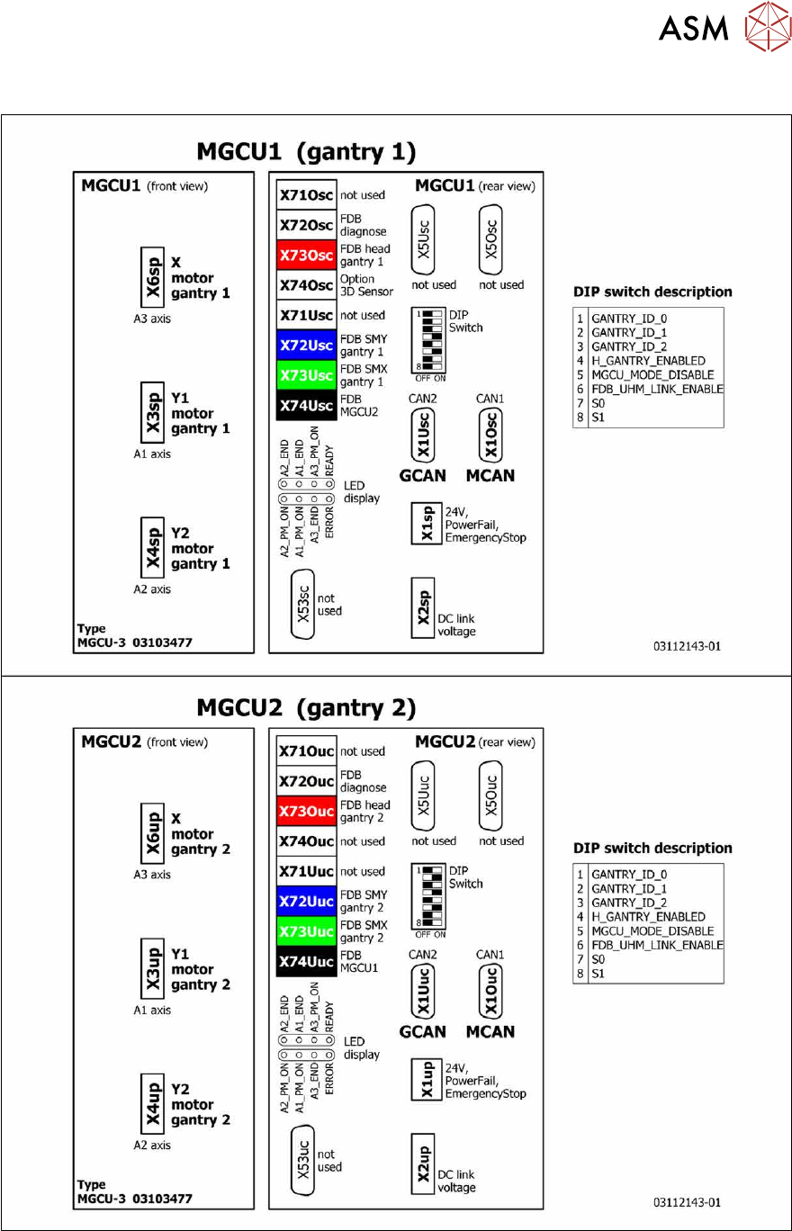
5.1.3 Overview of MGCU (Rxxxx)
Fig.89: Overview of MGCU