00198783-01_AI_Kit_TwinVHF_Gantry_SXV3_de_en.pdf - 第125页
3 Fitting the gantry 3.7 Final Work Assembly Instructions / Montageanleitung SIPLACE SX1/SX2 V3 Reconfiguration Kit Twin VHF mit Portal Reconfiguration Kit Twin VHF with Gantry 06/2020 125 Fig.56: Fitting the cover ► Fi…
3 Fitting the gantry
3.6 Connecting the Trailing Cable
124 Assembly Instructions / Montageanleitung SIPLACE SX1/SX2 V3 Reconfiguration Kit Twin VHF mit Portal
Reconfiguration Kit Twin VHF with Gantry 06/2020
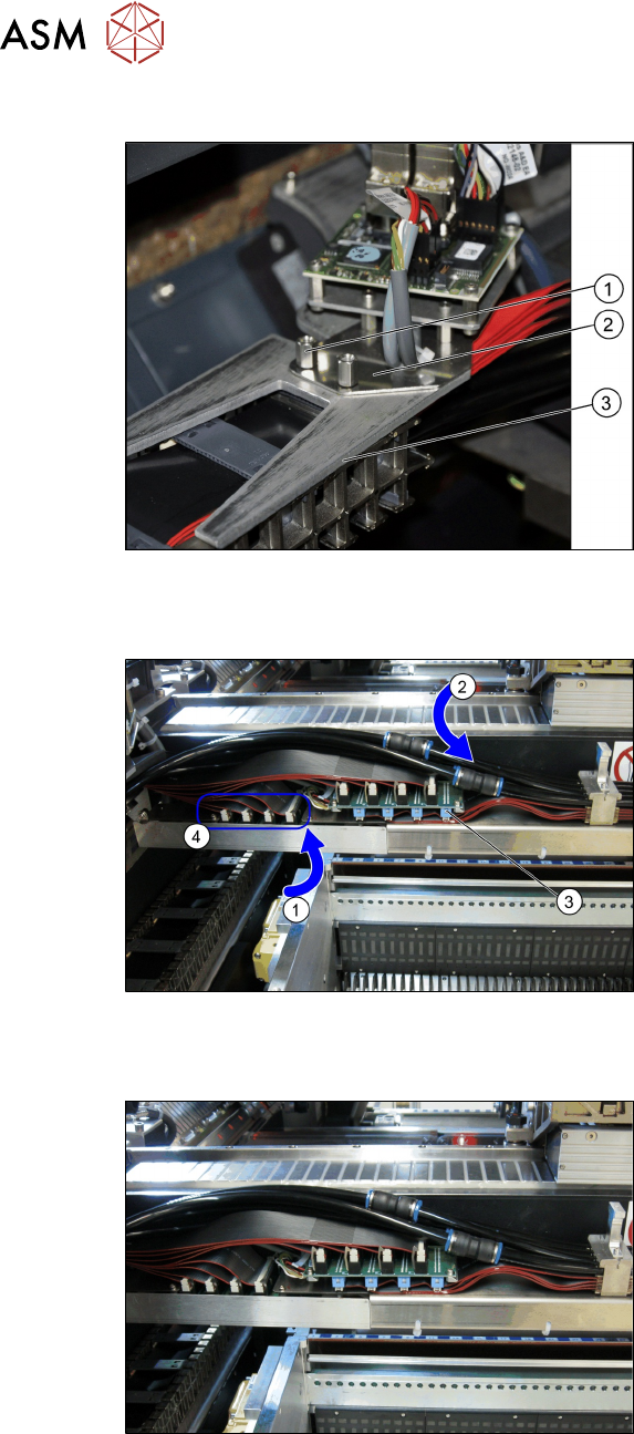
Trailing cable holder - overview
Fig.53: Trailing cable mount
1. Two hexagon spacer bolts M4 x 10
mm.
2. Gantry board holder
3. Trailing cable holder
► Remove the two hexagon spacer bolts
M4 x 10 mm on the trailing cable
holder.
► Hold the trailing cable holder from
below, on the gantry board holder.
► Screw the two hexagon spacer bolts
from above, into the trailing cable
holder.
► Secure the two hexagon spacer bolts
with Loctite 241
.
Restore the electrical and pneumatic connections
Fig.54: Electrical and pneumatic connections
► First connect the seven flat ribbon
cables (1)
to the boards for the gantry
interface of the X axis (3)
and the
gantry interface of the Y axis (4)
. The
sequence depends on the different
cable lengths. Work your way from
back to front.
► Remove the dummy plugs from the
pneumatic hose couplings.
► Connect the four pneumatic connec-
tions for the trailing cable to the gantry
connections (2)
. The sequence de-
pends on the different hose lengths.
Connections established
Fig.55: Arranging the connections
This diagram shows the precisely run and
correctly arranged connections.
3 Fitting the gantry
3.7 Final Work
Assembly Instructions / Montageanleitung SIPLACE SX1/SX2 V3 Reconfiguration Kit Twin VHF mit Portal
Reconfiguration Kit Twin VHF with Gantry 06/2020
125
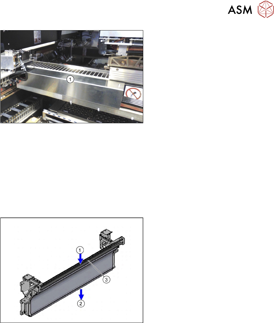
Fig.56: Fitting the cover
► Fit the cover (1) over the gantry inter-
face.
3.7 Final Work
3.7.1 Empty Tape Duct Intermediate Plate
If tapes with high components are processed, you will need to remove the empty tape duct interme-
diate plate when upgrading a gantry with SIPLACE TwinHead or SIPLACE CPP and stationary
camera.
If you are only using component with tapes up to 12mm, keep the intermediate plate in the empty
tape duct.
Fig.57: Tape duct
1. Inlet slot for empty tapes
2. Outlet slot for the empty tapes above
the pneumatic tape cutter
3. Partition plate for tapes < 12 mm (can
be removed for tapes > 12 mm)
3 Fitting the gantry
3.7 Final Work
126 Assembly Instructions / Montageanleitung SIPLACE SX1/SX2 V3 Reconfiguration Kit Twin VHF mit Portal
Reconfiguration Kit Twin VHF with Gantry 06/2020
3.7.2 Stowing the Gantry Carrier and the Prepared Case
Stowing the gantry carrier in the transportation crate
► Use the gantry lift to move the gantry carrier into the transportation crate.
► Fix the gantry carrier into place in the transportation crate, with the four fastening screws.
► Release the gantry carrier from the gantry lift and move the gantry lift to one side.
► Place the foam cover for the placement head in the transportation crate.
► Close the front and top cover on the transportation crate.
Placing assembly parts in the "Prepared" case
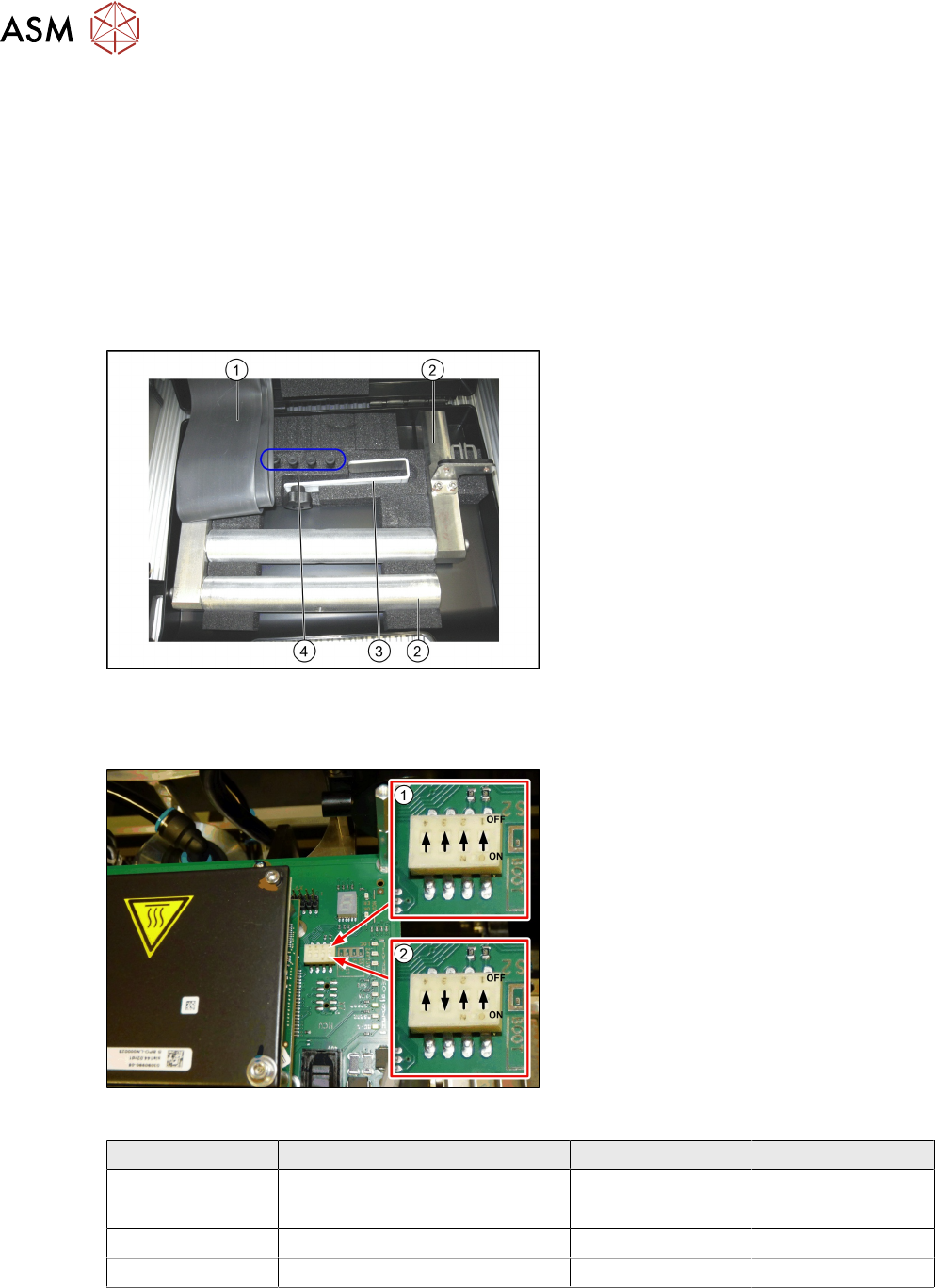
Fig.58: Prepared case
You have removed the following parts which
you will need to dismantle the gantry later
on. Keep these parts in the "Prepared" case:
1. Black plastic foil for trailing cable
2. The long end position buffer.
3. Trailing cable holder with knurled head
screw
4. Two transportation locks for the place-
ment head
●
A green lever as transportation lock for
the gantry
3.7.3 Checking the Gantry Coding
Fig.59: DIP switch gantry encoding for gantry 1 and 2
1. DIP switch for gantry 1
2. DIP switch for gantry 2
► Check the DIP switch for the gantry
coding of the locations on the head in-
terface.
Switch Designation Gantry 1 Gantry 2
1 DC/DC OFF OFF
2 FAN OFF OFF
3 P1 OFF ON
4 P0 OFF OFF