00198783-01_AI_Kit_TwinVHF_Gantry_SXV3_de_en.pdf - 第117页
3 Fitting the gantry 3.3 Assembling the SIPLACE Twin VHF Assembly Instructions / Montageanleitung SIPLACE SX1/SX2 V3 Reconfiguration Kit Twin VHF mit Portal Reconfiguration Kit Twin VHF with Gantry 06/2020 117 Fig.37: S…
3 Fitting the gantry
3.3 Assembling the SIPLACE Twin VHF
116 Assembly Instructions / Montageanleitung SIPLACE SX1/SX2 V3 Reconfiguration Kit Twin VHF mit Portal
Reconfiguration Kit Twin VHF with Gantry 06/2020
3.2.5 Fitting the MHCUs and base adapter for MHCU
► Fit the MHCUs onto the base adapter and then fit the base adapter onto the gantry.
Please read section 5.1.2
"Replacing the head adapter for the HCU and MHCU" [}146] and
the relevant chapter in the service manual for your machine.
3.3 Assembling the SIPLACE Twin VHF
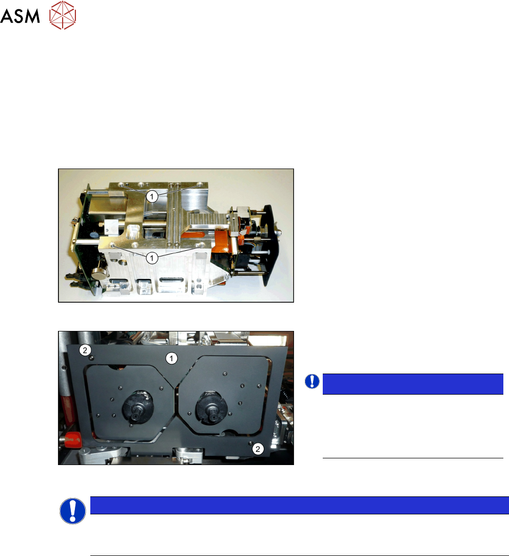
The SIPLACE Twin VHF is fitted to the gantry before the gantry is installed. It consists of two
identical Twin segments, which are fitted at an angle of 180°.
Fig.35: SIPLACE Twin VHF
Each module is fixed with four screws to the
head plate and is positioned with two pins.
► Lift the first module into position and
fasten this into place using a long Allen
key. Use the four M4x14screws(1)
.
► Repeat this step for the second mod-
ule.
Fig.36: Camera lens hood
► Fit the camera screen(1). This is
fastened into place using two black
screws(2)
.
NOTICE!
Black screws
Only use these screws to fix the cam-
era screen. This prevents reflection
when measuring components with the
stationary camera.
.
NOTICE
Hose and cable guidance
When performing the following steps, pay attention to the correct running of hoses and
cables. Refer to the diagrams for guidance.
3 Fitting the gantry
3.3 Assembling the SIPLACE Twin VHF
Assembly Instructions / Montageanleitung SIPLACE SX1/SX2 V3 Reconfiguration Kit Twin VHF mit Portal
Reconfiguration Kit Twin VHF with Gantry 06/2020
117
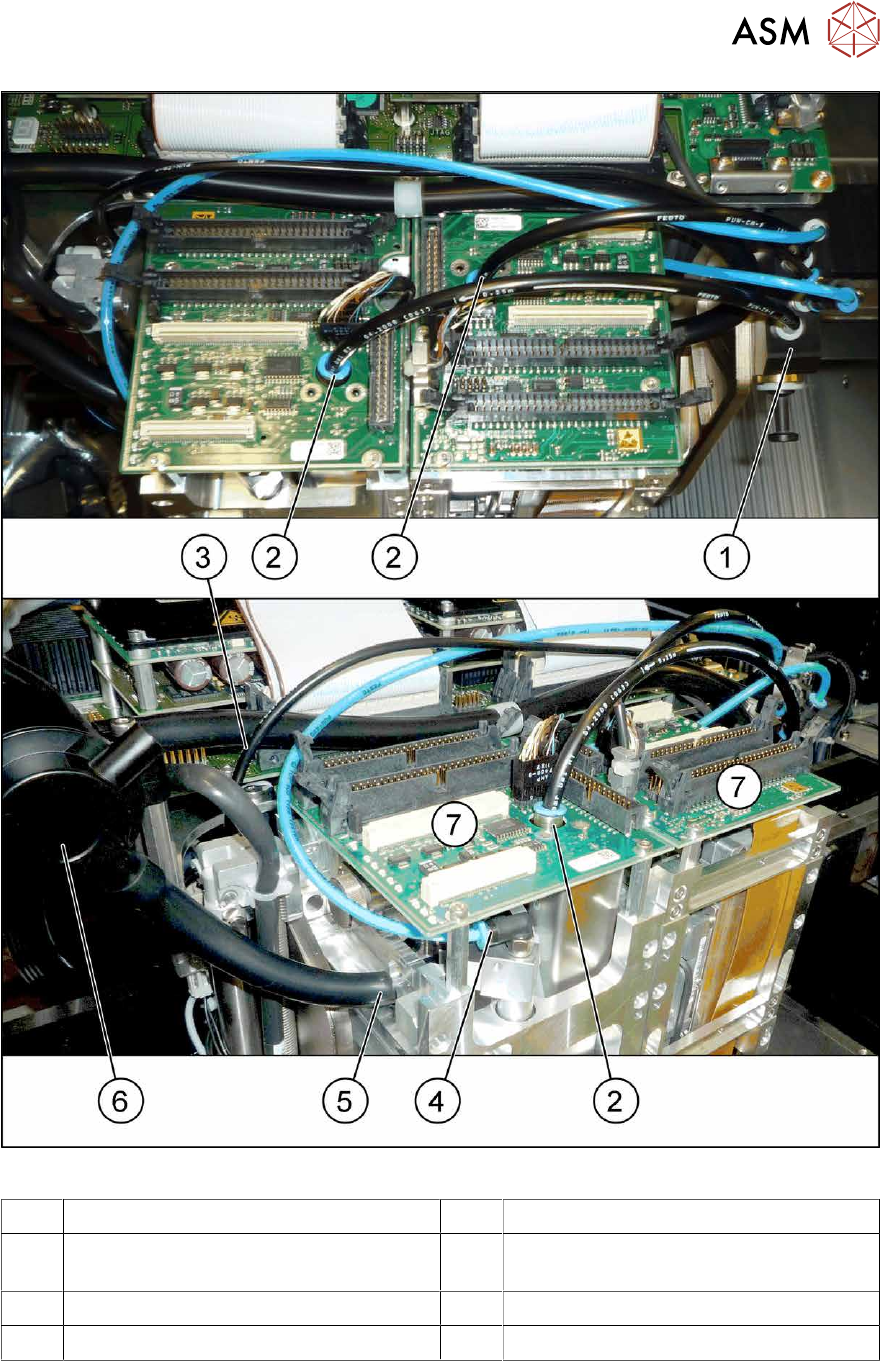
Fig.37: SX12 hoses for Twin VHF
1 Pneumatic distributor 2 Connection for pressure control valve
3 Hose to Pin Picker (Smart Pin Support
option)
4 Connection for return unit
5 Connection for exhaust tube 6 Silencer discharged air
7 Head boards
► Connect the discharged air connections for the two modules to the silencer.
► Connect the two return units, vacuum generator and pressure control valves with the pneu-
matic distributor.
► Connect the head boards with the base adapter, using two flat ribbon cables in each case.
3 Fitting the gantry
3.4 Converting the Cover
118 Assembly Instructions / Montageanleitung SIPLACE SX1/SX2 V3 Reconfiguration Kit Twin VHF mit Portal
Reconfiguration Kit Twin VHF with Gantry 06/2020
3.4 Converting the Cover
When using the SIPLACE WPC5/6 for high components, you need to convert the cover. The new
cover has a recess for the SIPLACE WPC on the disk.
CAUTION
No SIPLACE WPC
If no SIPLACE WPC is fitted, you will not be able to feed in components with a height of 40
mm.
The SIPLACE cover may not be converted if there is no WPC!
To do so, proceed as follows:
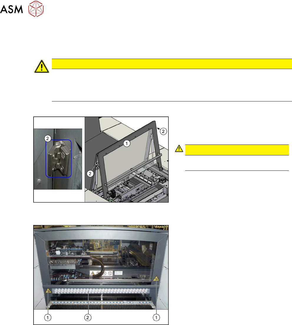
Fig.38: Cover with hinges
1. Cover
2. Hinges on the cover (2x)
CAUTION!
You may need to enlist the help of a
second person for this job.
.
► Loosen the screws fastening the hinges
at the top of the cover. While doing this,
hold the front section of the cover tight.
► Remove the front section of the cover.
► Insert the new front section of the cover
into the machine and screw into place.
Fig.39: Label on the cover
1. Danger of crushing label (2x)
2. Barcode adhesive label
► Attach the following adhesive labels to
the new cover. For their exact posi-
tions, refer to the old cover.