00198783-01_AI_Kit_TwinVHF_Gantry_SXV3_de_en.pdf - 第145页
5 Appendix 5.1 Excerpts from the Service Manual Assembly Instructions / Montageanleitung SIPLACE SX1/SX2 V3 Reconfiguration Kit Twin VHF mit Portal Reconfiguration Kit Twin VHF with Gantry 06/2020 145 5 Appendix 5.1 Exce…
4 Dismantling a Gantry
4.3 Checklist
144 Assembly Instructions / Montageanleitung SIPLACE SX1/SX2 V3 Reconfiguration Kit Twin VHF mit Portal
Reconfiguration Kit Twin VHF with Gantry 06/2020
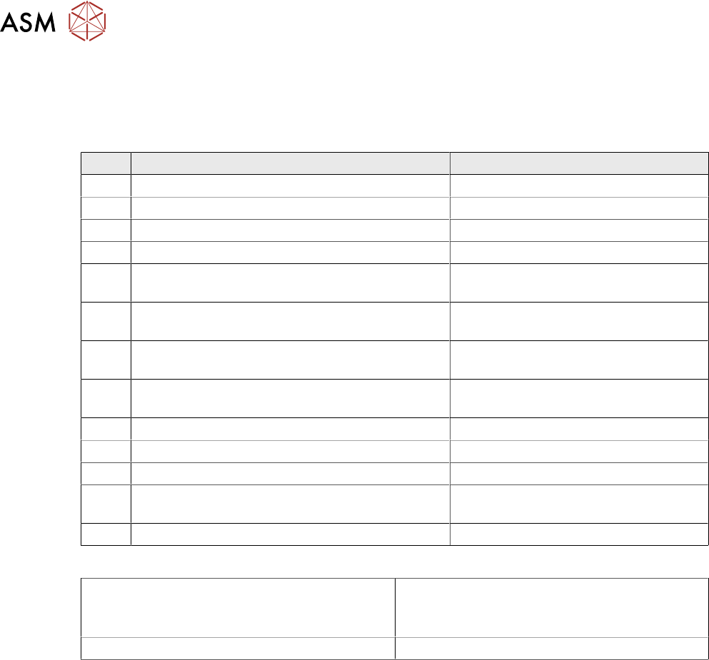
4.3 Checklist
► Put this check list in the machine logbook.
Gantry dismantled (downgrade)
Step Action Who?
1 Gantry removed? Customer in line with assembly guide
2 Is the gantry secured in the gantry carrier? Customer in line with assembly guide
3 Head secured in center of gantry? Customer in line with assembly guide
4 Are the correct end position buffers fitted? Customer in line with assembly guide
5 Has the trailing cable been packed correctly and
fixed in the machine?
Customer in line with assembly guide
6 Has the stationary camera (optional) been dis-
mantled, if necessary?
Customer in line with assembly guide
7 Have the camera connections been unplugged
from the box PC?
Customer in line with assembly guide
8 Has the nozzle changer been dismantled, if ne-
cessary
Customer in line with assembly guide
9 Is the reject bin fitted? Customer in line with assembly guide
10 Have all tools been removed from the machine? Customer in line with assembly guide
11 Are the doors screwed? Customer in line with assembly guide
12 Is the machine switched on and ready for opera-
tion?
Customer in line with assembly guide
13 Have all calibration steps been performed? Customer in line with assembly guide
Date Signature
5 Appendix
5.1 Excerpts from the Service Manual
Assembly Instructions / Montageanleitung SIPLACE SX1/SX2 V3 Reconfiguration Kit Twin VHF mit Portal
Reconfiguration Kit Twin VHF with Gantry 06/2020
145
5 Appendix
5.1 Excerpts from the Service Manual
The following chapters are excerpts from the service manual. For more information, refer to the full
service manual for your machine.
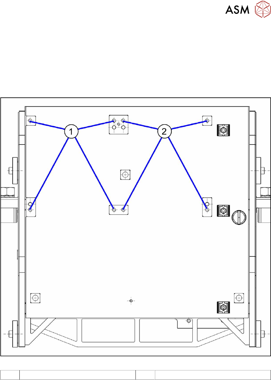
5.1.1 Installation Positions on the Twin VHF Head Plate
Fig.85: Installation positions on the Twin VHF head plate
1 Installation position Twin VHF segment 1 2 Installation position Twin VHF segment 2
5 Appendix
5.1 Excerpts from the Service Manual
146 Assembly Instructions / Montageanleitung SIPLACE SX1/SX2 V3 Reconfiguration Kit Twin VHF mit Portal
Reconfiguration Kit Twin VHF with Gantry 06/2020
5.1.2 Replacing the head adapter for the HCU and MHCU
NOTICE
SIPLACE C&P20P
The following additional conditions must be fulfilled for operating a SIPLACE C&P20P:
► The base adapter needs at least FS06.
► Make sure to use MHCU [03090990-xx].
► You find a complete list of the prerequisites in section Replacing the C&P20 P Head.
Parts, equipment and tools
The head adapter version needed depends on the head which is installed:
03065868-xx Head adapter HCU for SIPLACE CPP and SIPLACE C&P20A
(consists of: 1x PCB/B base adapter C&P [03055516-xx] and 1x MHCU
[03090990‑xx])
03065969-xx Head adapter HCU for SIPLACE Twin (VHF TwinHead)
(consists of: 1x PCB/B base adapter TWIN [03055517-xx] and 2x MHCU
[03090990‑xx])
03090990-xx MHCU assembly, compatible
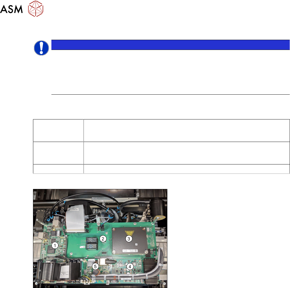
Overview
Fig.86: Boards on the gantry
1. Vision head interface
2. Head adapter (shows the CPx version
with a MHCU)
3. 1x MHCU (2x for Twin)
4. Head interface
5. Sensor module
Removal
► Switch off the machine, disconnect it from the power supply and secure it to prevent
unauthorized reactivation.
1.2 "Preparatory work..." [}85]
► If there is a cover above the boards, dismantle it.
► Unplug all electrical connections. You may want to mark the positions of these connections to
make clear assignment easier later on.