00198783-01_AI_Kit_TwinVHF_Gantry_SXV3_de_en.pdf - 第127页
3 Fitting the gantry 3.7 Final Work Assembly Instructions / Montageanleitung SIPLACE SX1/SX2 V3 Reconfiguration Kit Twin VHF mit Portal Reconfiguration Kit Twin VHF with Gantry 06/2020 127 3.7.4 Fitting the cover Fig.60…
3 Fitting the gantry
3.7 Final Work
126 Assembly Instructions / Montageanleitung SIPLACE SX1/SX2 V3 Reconfiguration Kit Twin VHF mit Portal
Reconfiguration Kit Twin VHF with Gantry 06/2020
3.7.2 Stowing the Gantry Carrier and the Prepared Case
Stowing the gantry carrier in the transportation crate
► Use the gantry lift to move the gantry carrier into the transportation crate.
► Fix the gantry carrier into place in the transportation crate, with the four fastening screws.
► Release the gantry carrier from the gantry lift and move the gantry lift to one side.
► Place the foam cover for the placement head in the transportation crate.
► Close the front and top cover on the transportation crate.
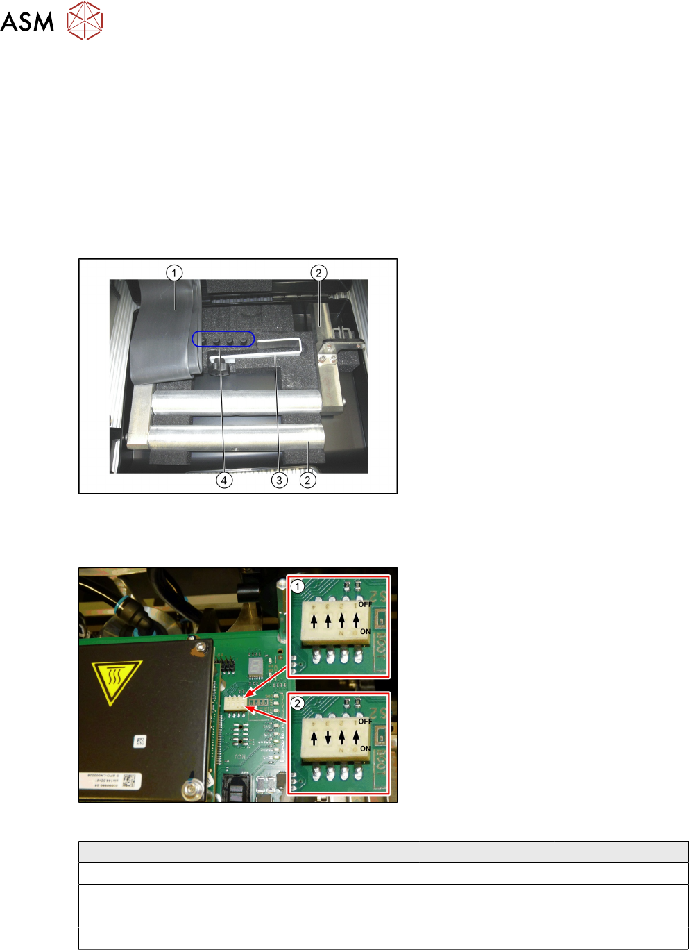
Placing assembly parts in the "Prepared" case
Fig.58: Prepared case
You have removed the following parts which
you will need to dismantle the gantry later
on. Keep these parts in the "Prepared" case:
1. Black plastic foil for trailing cable
2. The long end position buffer.
3. Trailing cable holder with knurled head
screw
4. Two transportation locks for the place-
ment head
●
A green lever as transportation lock for
the gantry
3.7.3 Checking the Gantry Coding
Fig.59: DIP switch gantry encoding for gantry 1 and 2
1. DIP switch for gantry 1
2. DIP switch for gantry 2
► Check the DIP switch for the gantry
coding of the locations on the head in-
terface.
Switch Designation Gantry 1 Gantry 2
1 DC/DC OFF OFF
2 FAN OFF OFF
3 P1 OFF ON
4 P0 OFF OFF
3 Fitting the gantry
3.7 Final Work
Assembly Instructions / Montageanleitung SIPLACE SX1/SX2 V3 Reconfiguration Kit Twin VHF mit Portal
Reconfiguration Kit Twin VHF with Gantry 06/2020
127
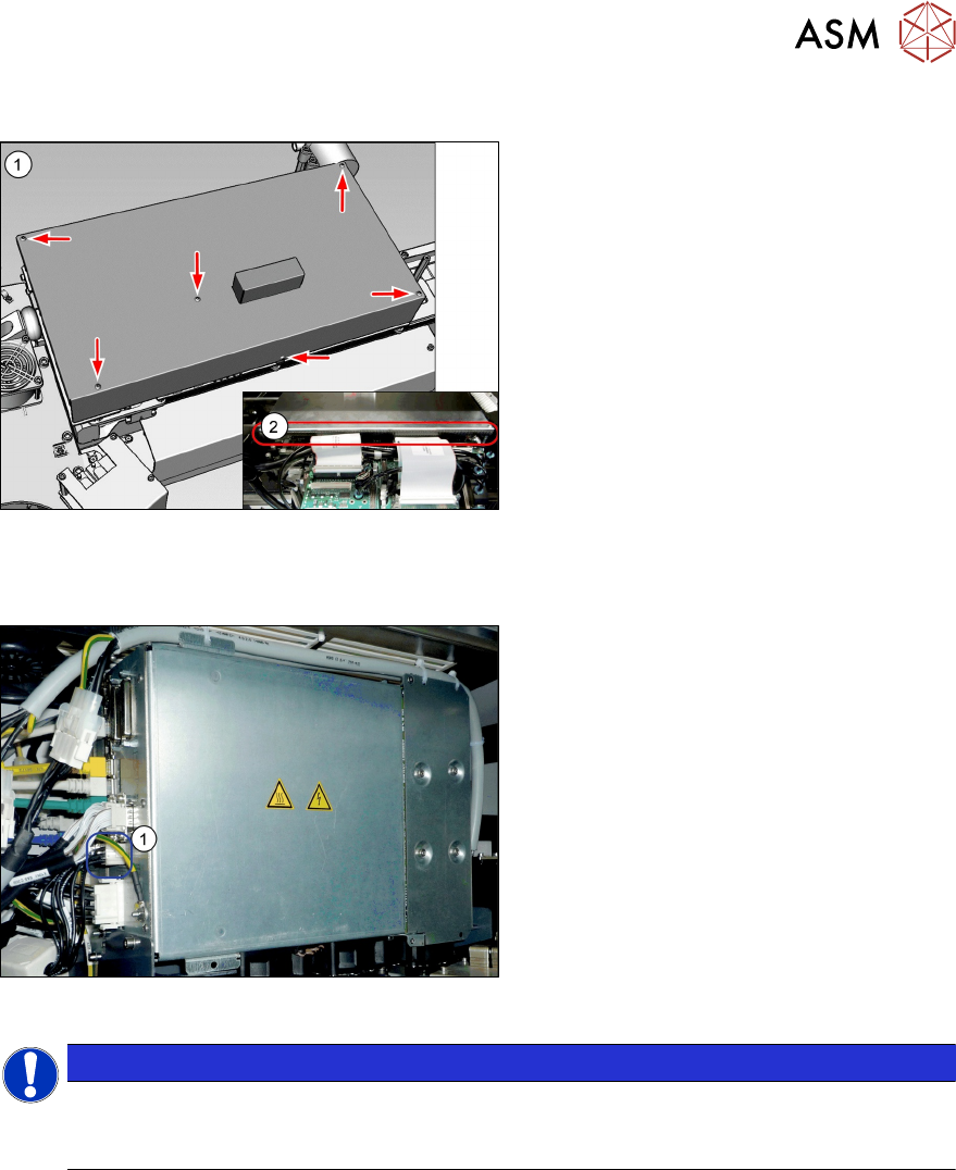
3.7.4 Fitting the cover
Fig.60: Cover
► Fit the cover(1) on the boards.
► VHF heads also need edge protec-
tion(2)
to be present.
3.7.5 Note MGCU
Fig.61: MGCU supply cable [03068134-xx]
► Please check the connection of the
MGCU power cable with the connector
X1up (1)
to ensure a correct start-up of
the machine.
NOTICE
Dismantling a gantry
The connector X1up has to be disconnected from the MGCU, if the gantry is dismantled
later on.
See also
2 5.1.3 "Overview of MGCU (Rxxxx)" [}149]
3 Fitting the gantry
3.7 Final Work
128 Assembly Instructions / Montageanleitung SIPLACE SX1/SX2 V3 Reconfiguration Kit Twin VHF mit Portal
Reconfiguration Kit Twin VHF with Gantry 06/2020
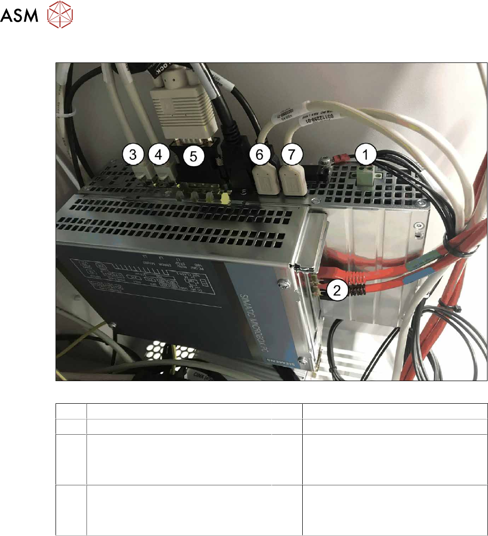
3.7.6 Checking the Camera Cable
Fig.62: Rear side BoxPC 427D
1 Power supply DC 24V 2 GigE ethernet adapter PCI-E
3 LAN 1: CIN Box 4 LAN 2: connection for line computer
5 DVI/VGA monitor connection
(connection monitor 1)
6 USB 2 – connection for an external DVD
drive
USB 4: X63 - connection for monitor 2
multitouch
7 USB 0: connection for keyboard/touch-
screen (connection to USB hub)
USB 1: X60 connection for monitor 1
multitouch
► Check whether the camera cable is connected to the GigE Ethernet adapter of the box PC.
Pay attention to the correct connections (see labeling on the GigE Ethernet adapter).