IPC-D-279 EN.pdf - 第14页
1.3.7 Testing Section 8.0 details the various testing strategies, their purposes and their impact on reliability . Also discussed are design for testability considerations. Checklists for DfT from various sources are pro…

Test, storage and transportation need to be considered at
both component and assembly levels as well as before,
during, and after the assembly process.
1.2.4 Defining the Product Environment For each envi-
ronment, in 1.2.3, it is critical to identify, characterize and
quantify the parameters listed below:
• Temperature Range
• Time at Temperature
• Temperature Rate of Change
• Kind and number of temperature cycles
• Duty Cycle
• Humidity (moisture) exposure
• Atmospheric pressure conditions (earth, space, both)
• Vibration and shock
• ESD, EOS, EMC, EMI and high voltage exposures
and requirements
• Chemical exposures (flux, solvents, salt spray, NBC,
decontamination, etc.)
• Radiation (Ionizing, light, UV)
• Contamination (dust, oil, paper)
• Pressure conditions
When the life environments have been identified and
defined, the engineering team is prepared to analyze and
select the materials, components, assembly processes, ther-
mal management and test strategies required.
1.3 Document Organization This document has been
organized to provide the reader with consistent information
on the various aspects of surface mount technology printed
board assemblies and identifies the parameters that need to
be addressed. Each section serves a specific function in the
SMT design process. The body of this document addresses
general design guidelines specific to SMT. The appendices
contain detailed information of SMT design or common
design considerations between SMT and through hole pro-
cesses.
1.3.1 Applicable Documents Section 2.0 lists only those
documents related to surface mount technology and reli-
ability which are mentioned in the text. The design engi-
neers need to know about the primary documents which
underlie the text. The bibliography, Section 9, lists docu-
ments by interest area and some entries are duplicated;
there are many more documents of use and available to the
designer. This lists only those documents used day to day.
1.3.2 Design for Reliability of SM Assemblies Section
3.0, together with Sections 4.0 and 5.0, considers the broad
range of environmental stresses to which the printed wiring
assembly (PWA) must be robust during its life cycle (life
cycle environment) and some specific mitigation tech-
niques that may be used. A separate Appendix D for SM
thermal design augments Appendix A for the DfR of solder
attachments and Appendix B for DfR of plated-through
vias (PTVs). Appendix C provides DfR information for
insulation resistance aspects. Appendix E provides DfR
information for insulation resistance aspects Appendix E
relates environmental stresses and the corresponding PWA
and component responses. Appendix G provides material
CTE data. Appendix I describes solvent related stresses on
plastics and metals. Appendix L deals with corrosion.
Appendix M discusses solder joint variability. Appendix N
deals with adhesives, solder masks and conformal coatings.
Appendix O covers the special requirements for high alti-
tude and aerospace applications.
1.3.3 Substrates Section 4.0 covers rigid and flexible
substrates and their impact on SM assembly reliability.
Data on material parameters and tradeoffs is provided. Sub-
strate related issues such as thermal expansion mismatch,
moisture absorption, and PTH-via thermal stress are cov-
ered. Related materials CTE data is provided in Appendix
G. Appendix N deals with adhesives, solder masks and
conformal coatings. A detailed DfR treatment for PTVs is
provided in Appendix B.
1.3.4 Components Section 5.0 covers components,
component-related design issues, and component-process
interactions of concern to the designer as well as to the
process engineer. Appendix E relates environmental
stresses and the corresponding PWA and component
responses. Appendix F provides a ready reference to sur-
face mount plastic package cracking during SM reflow and
to methods for mitigating those effects. Appendix H pro-
vides a ready reference to the electrostatic discharge sus-
ceptibility groupings of various component families.
1.3.5 Attachment Materials and Coatings Section 6.0
addresses attachment materials and polymer coatings. The
attachment materials include solder, electrically conductive
adhesives, thermally conductive adhesives and structural
adhesives. The polymer coatings include solder mask con-
formal coating.
1.3.6 Assembly Processes and DfM Section 7.0 pro-
vides an overview of the assembly processes used in sur-
face mount assemblies and highlights the specific reliabil-
ity issues associated with each of the individual processes,
including design for manufacturability (DfM) consider-
ations. The surface mount processing conditions may be
the most severe that the assembly ever sees during its life
cycle, not only in terms of temperature but shock and flex-
ure as well. A DfM checklist is provided listed in Appen-
dix K together with pointers to DfM assessment tools in
software. A detailed list of solvent/plastic/metal compat-
ibilities is provided in Appendix I.
IPC-D-279 July 1996
2
1.3.7 Testing Section 8.0 details the various testing
strategies, their purposes and their impact on reliability.
Also discussed are design for testability considerations.
Checklists for DfT from various sources are provided in
Appendix J.
1.4 Terms and Definitions Terms and definitions used
here are in accordance with IPC-T-50, and IPC-SM-785
except as otherwise specified.
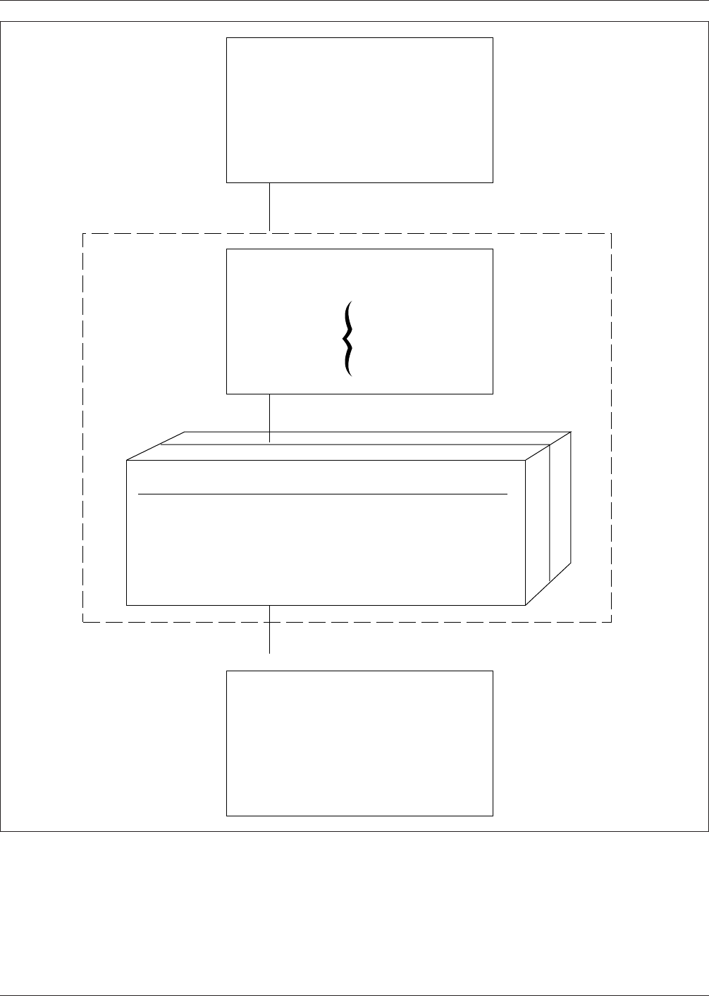
IPC-279-01
Figure 1−1 General Design Steps
▼
▼
▼
1. Years of Service
2. Acceptable Failure Rate Limit
3. Repair/Replacement Strategy
Identify Reliability Reqts.
Levels:
•
Component
•
Assembly
Identify Life Environment
Phases:
•
Storage
•
Transportation
•
Processing
•
Testing
•
Operating
Temp. Range
•
•
•
Vibration/Shock
Identify Storage Env.
Transp. Env.
Proc.
ESD
•
•
•
Atmosphere
Analyze & Select
•
Components
•
Materials
•
Assembly Processes
•
Test Strategy
•
Thermal Mgt. Strategy
•
Solder Attachments
•
PWB Design
July 1996 IPC-D-279
3
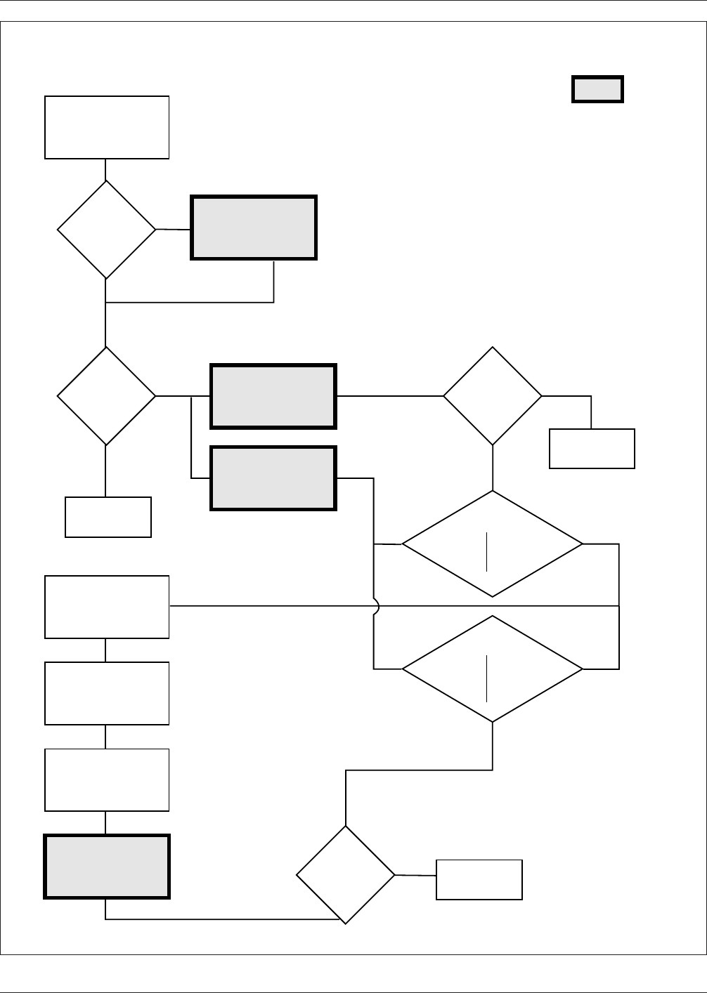
IPC-279-02
Figure 1−2 Flow Chart for Reliability Assurance Processes
▼
▼
▼
▼
▼
▼
▼
▼
▼
▼
▼
▼
▼
▼
▼
▼
▼
▼
▼
▼
▼
▼
▼
▼
▼
▼
▼
▼
Determine
missing
data.
Is
information
complete enough
for reliability
analysis?
Is
reliability in
Appendices
A, B & C
Estimate product
reliability
Appendices A, B & C
Redesign product.
Redefine
requirements.
Is
estimated
reliability
adequate?
Finish
Finish
Solution:
Redesign
Redefine
Reduce
Uncertainties
Solution:
Redesign
Redefine
Review test
program for
correct-
ness
Finish
Is
reliability
adequate
?
Collection of all
available inform-
ation & requirements
Flow Chart for Reliability Assurance Processes
Define proper
test, conditions,
IPC-SM-785
Accelerated
reliability
test(s)
Evaluate results
Failure Mode
Analysis
Estimate product
reliability from
test results
▼
Yes
No
Yes
Yes
No
No
Yes
No
Main Focus of Document
IPC-D-279 July 1996
4