IPC-D-279 EN.pdf - 第57页
40//60°C) = 1000//2650 cycles, n(LCCC) = 30, N f (0.5%, LCCC, ∆ T = 40//60°C) = 127,000//15,400 cycles, β (LCCC) = 2, n(CC1820) = 100, N f (0.5%, CC1820, ∆ T = 40//60°C) = 43,000//21,000 cycles, β (CC1820) = 4; =>F ∑ …

beyond Class 2 requirements is the reliability diminished.
However, solder joints not properly wetted, can prema-
turely fail both as the result of mechanical and thermal
cyclic loading [Refs. A-9: 1,31].
Voids in the solder joints are generally regarded as not
constituting a reliability threat [Ref. A-9: 48]. Possible
exceptions are large voids reducing the solder joint cross-
section enough to reduce a required thermal heat transfer
function, and voids in high-frequency applications where
the voids can cause signal deterioration.
A-7.2 Screening Recommendations
Effective screening procedures need to be capable of caus-
ing the failure of latent solder joint defects, i.e., weak inad-
equately wetted solder joints, without causing significant
damage to high quality solder joints.
The best recommendation is random vibration (6-10 grams
for 10-20 minutes), preferably at low temperature, e.g.,
-40°C. This loading does not damage good solder joints,
but overstresses weakly bonded ones [Ref. A-9: 1].
Thermal shock can also be successfully used, however
some damage to good solder joints can be expected, par-
ticularly for larger components.
A-8.0 STEP-BY-STEP NUMERICAL EXAMPLE RELATING
REQUIRED DESIGN LIFE TO ACCELERATED RELIABIL-
ITY TEST RESULTS
This numerical example illustrates how the reliability of an
electronic system in the field can be assessed by using the
Design for Reliability (DfR) process in Appendix A or the
results of accelerated test results carried out as per IPC-
SM-785, Guidelines for Accelerated Reliability Testing of
Surface Mount Solder Attachments.
For example the following information is assumed:
Product:
Computer for Navy artillery—Use Category 6 in Table
A-1,
Design life = 10 years (= 3650 thermal cycles at 1 cycle/
day),
Component-external daily temperature cycles: 45 to 85°C
(∆T = 40°C) for 100 days/year and 25 to 85°C (∆T=
60°C) for 265 days/year (in the following text, the data
and results for these two loading conditions appear
before and after ‘‘//’’ respectively),
Acceptable cumulative failure probability at end of 10
years, x = 0.5%,
Largest leaded component:
68 I/O 50-mil pitch ceramic chip carrier (LCCC), α
C
= 6.3
ppm/°C (6.3x10
-6
/°C), dissipating 0.8 W raising the
component operating temperature to 93°C, with side-
brazed copper alloy compliant leads with a diagonal
lead stiffness of K
D
= 52 lb/in,
Largest leadless component:
CC1820 chip capacitor, α
C
= 6.8 ppm/°C,
Substrate:
Low CTE multilayer board, α
S
= 10.5 ppm/°C.
Reliability Estimates for Individual Components:
Ceramic Chip Carrier:
The input parameters into Eq. A-4 are: F = 1.0, K
D
=52
lb/in, L
D
= 0.674 in, ∆(α∆T) = 117.6x10
-6
//201.6x10
-6
(α
C
= 6.3 ppm/°C, α
S
= 10.5 ppm/°C, T
C
= 93°C, T
S
=
85°C, T
C,0
=T
S,0
= 45//25°C), A = 900x10
-6
in
2
,h=
0.005 in;
-> ∆D(leaded) = 5.459x10
-4
//1.604x10
-3
at ∆T = 40//60°C,
respectively.
The input parameters into Eq. A-2 are: T
SJ
= 67//57°C (T
C
= 93°C, T
S
= 85°C, T
C,0
=T
S,0
= 45//25°C), t
D
= 715
min;
-> c = −0.4751//−0.4691 at ∆T = 40//60°C, respectively.
Using these results in Eq. A-1 gives:
=> N
f
(50%) = 1,490,000//181,000 cycles at ∆T = 40//60°C,
respectively.
Using these results in Eq. A-8 with x = 0.5% and β =2
gives:
=> N
f
(0.5%) = 127,000//15,400 cycles at ∆T = 40//60°C,
respectively.
CC1820 Chip Capacitor:
The input parameters into Eq. A-3 are: F = 0.7, L
D
= 0.080
in, ∆(α∆T) = 148.0x10
-6
(α
C
= 6.8 ppm/°C, α
S
= 10.5
ppm/°C, T
C
= 85°C, T
S
= 85°C, T
C,0
=T
S,0
= 45//25°C),
h = 0.005 in;
-> ∆D(leadless) = 1.658x10
-3
//2.486x10
-3
at ∆T = 40//
60°C, respectively.
The input parameters into Eq. A-2 are: T
SJ
= 65//55°C (T
C
= 85°C, T
S
= 85°C, T
C,0
=T
S,0
= 45//25°C), t
D
= 715
min;
-> c = −0.4739//−0.4679 at ∆T = 40//60°C, respectively.
Using these results in Eq. A-1 gives:
=> N
f
(50%) = 148,000//73,000 cycles at ∆T = 40//60°C,
respectively.
Using these results in Eq. A-8 with x = 0.5% and β =4
gives:
=> N
f
(0.5%) = 43,000//21,000 cycles at ∆T = 40//60°C,
respectively.
Cumulative Damage Ratios for Multiple Cyclic Loads
The input parameters into Eq. A-10 are: N(∆T = 40//60°C)
= 1000//2650 cycles, N
f
(0.5%, LCCC, ∆T = 40//60°C)
= 127,000//15,400 cycles, N
f
(0.5%, CC1820, ∆T = 40//
60°C) = 43,000//21,000 cycles,
=> CDR(0.5%, LCCC) = 0.18 and CDR(0.5%, CC1820) =
0.15.
Reliability Estimates for Product with Multitude of Compo-
nents:
The input parameters into Eq. A-11 are: x = 0.5%, N(∆T=
July 1996 IPC-D-279
45
40//60°C) = 1000//2650 cycles, n(LCCC) = 30,
N
f
(0.5%, LCCC, ∆T = 40//60°C) = 127,000//15,400
cycles, β(LCCC) = 2, n(CC1820) = 100, N
f
(0.5%,
CC1820, ∆T = 40//60°C) = 43,000//21,000 cycles,
β(CC1820) = 4;
=>F
∑
(N = 3650) = 0.5%.
Thus, this design would just meet the reliability require-
ment of x ≤0.5% at the end of 10 years of service.
Accelerated Testing:
Test Components:
8 chip carriers (LCCC), 68 I/O 50-mil, α
C
= 6.3 ppm/°C
(measured), internally daisy-chained to allow indepen-
dent monitoring of each LCCC side (
1
⁄
4
of LCCC), with
side-brazed copper alloy compliant leads with a diago-
nal lead stiffness of K
D
= 52 lb/in (calculated), 256 chip
capacitors CC1820, α
C
= 6.8 ppm/°C (measured), with
metallization caps shorted with conductive epoxy on
capacitor top,
Test Substrate:
FR-4 multilayer board, α
S
= 16.0 ppm/°C (measured)
for greater CTE-mismatches and greater test accelera-
tion, test printed board lay-out provides for independent
continuity monitoring of each side of each chip carrier
(LCCC) and for continuity monitoring of groups of 8
chip capacitors (CCs) daisy-chained together. Confor-
mal Coating: Test vehicles are not conformally coated.
Test Parameters:
Temperature cycling from 0°C to 100°C at 24 cycles/
day, t
D
= 15 min, ∆T = 100°C and T
SJ
= 50°C.
Results of Accelerated Reliability Test:
N
f
(50%) = 982 and 6310 accelerated cycles-to-failure for
the individual LCCC sides and the 8 daisy-chained
CC1820s, respectively. Applying the partition correction
from Equation 16 in IPC-SM-785 results in N
f
(50%) =
491 and 10612 accelerated cycles-to-failure for the
actual LCCC and the CC1820 component attachments,
respectively.
Reliability Estimates by Extrapolation of Accelerated Test
Results:
Ceramic Chip Carrier:
The input parameters into Eq. A-4 are for the test: F =
1.0, K
D
= 52 lb/in, L
D
= 0.674 in, ∆(α∆T) = 970.0x10
-6
(α
C
= 6.3 ppm/°C, α
S
= 16.0 ppm/°C, T
C
=T
S
= 100°C,
T
C,0
=T
S,0
= 0°C), A = 900x10
-6
in
2
, h = 0.005 in;
-> ∆D(test) = 3.714x10
-2
.
and for the field use: F = 1.0, K
D
= 52 lb/in, L
D
= 0.674 in,
∆(α∆T) = 117.6x10
-6
//201.6x10
-6
(α
C
= 6.3 ppm/°C, α
S
= 10.5 ppm/°C, T
C
= 93°C, T
S
= 85°C, T
C,0
=T
S,0
=
45//25°C), A = 900x10
-6
in
2
, h = 0.005 in;
-> ∆D(use) = 5.459x10
-4
//1.604x10
-3
at ∆T = 40//60°C,
respectively.
The input parameters into Eq. A-2 are for the test: T
SJ
=
50°C (T
C
=T
S
= 100°C, T
C,0
=T
S,0
= 0°C), t
D
=15
min;
-> c(test) = −0.4160;
and for the field use: T
SJ
= 67//57°C (T
C
= 93°C, T
S
=
85°C, T
C,0
=T
S,0
= 45//25°C), t
D
= 715 min;
-> c(use) = −0.4751//−0.4691 at ∆T = 40//60°C, respec-
tively.
Using these results in Eq. A-12 in IPC-SM-785 with
N
f
(test, 50%) = 491 cycles gives:
=> N
f
(use, 50%) = 1,500,000//183,000 cycles at ∆T = 40//
60°C, respectively.
CC1820 Chip Capacitor:
The input parameters into Eq. A-3 are for the test: F =
0.7, L
D
= 0.080 in, ∆(α∆T) = 920.0x10
-6
(α
C
= 6.8
ppm/°C, α
S
= 16.0 ppm/°C, T
C
=T
S
= 100°C, T
C,0
=
T
S,0
= 0°C), h = 0.005 in;
-> ∆D(test) = 1.030x10
-2
.
and for the field use: F = 0.7, L
D
= 0.080 in, ∆(α∆T) =
148.0x10
-6
//222.0x10
-6
(α
C
= 6.8 ppm/°C, α
S
= 10.5
ppm/°C, T
C
=T
S
= 85°C, T
C,0
=T
S,0
= 45//25°C), h =
0.005 in;
-> ∆D(use) = 1.658x10
-3
//2.486x10
-3
at ∆T = 40//60°C,
respectively.
The input parameters into Eq. A-2 are for the test: T
SJ
=
50°C (T
C
=T
S
= 100°C, T
C,0
=T
S,0
= 0°C), t
D
=15
min;
-> c(test) = −0.4160;
and for the field use: T
SJ
= 65//55°C (T
C
=T
S,0
= 85°C,
T
C,0
=T
S,0
= 45//25°C), t
D
= 715 min;
-> c(use) = −0.4739//−0.4679 at ∆T = 40//60°C, respec-
tively.
Using these results into Eq. A-12 in IPC-SM-785 with
N
f
(test, 50%) = 10,612 cycles gives:
=> N
f
(use, 50%) = 148,000//73,000 cycles at ∆T = 40//
60°C, respectively.
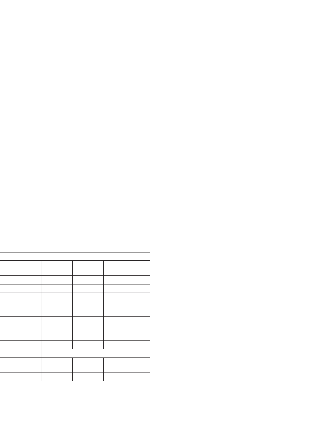
Cycles-To-Failure for Daisy-Chains
Failure
No.
12345678
1
⁄
4
LCCC 146 196 388 418 486 540 568 628
8 CC1820 2718 3463 3826 4161 4397 4631 4738 5022
Failure
No.
9 10111213141516
1
⁄
4
LCCC 676 684 690 820 850 878 902 926
8 CC1820 5206 5372 5489 5598 5823 5978 6073 6223
Failure
No.
17 18 19 20 21 22 23 24
1
⁄
4
LCCC 1038 1044 1096 1122 1206 1214 1298 1350
8 CC1820 6397 Test terminated at 6,400 cycles
Failure
No.
25 26 27 28 29 30 31 32
1
⁄
4
LCCC 1386 1480 1536 1602 1716 1840 2002 2432
8 CC1820 Test terminated at 6,400 cycles
IPC-D-279 July 1996
46

Conclusions:
The two components analyzed have large reliability mar-
gins for this use environment; a product with 30 chip carri-
ers and 100 CC1820s would just reach a cumulative failure
probability of 0.5% after 10 years.
Excellent agreement between the reliability estimates from
analytical reliability model and from extrapolation from the
results of accelerated testing is shown.
A-9.0 REFERENCES
1. Engelmaier, W., ‘‘Surface Mount Solder Joint Reliabil-
ity: Issues, Design, Testing, Prediction’’ Workshop
Notes, Engelmaier Associates, Inc., Mendham, NJ,
1995.
2. Engelmaier, W., ‘‘Effects of Power Cycling on Lead-
less Chip Carrier Mounting Reliability and Technol-
ogy,’’ Proc. Int. Electronics Packaging Conf. (IEPS),
San Diego. CA. November 1982, p. 15.
3. Engelmaier, W., ‘‘Functional Cycles and Surface
Mounting Attachment Reliability,’’ Surface Mount
Technology, ISHM Technical Monograph Series 6984-
002. The International Society for Microelectronics,
Silver Spring, MD, 1984, p. 87.
4. Engelmaier, W., and A. I. Attarwala, ‘‘Surface-Mount
Attachment Reliability of Clip-Leaded Ceramic Chip
Carriers on FR-4 Circuit Boards,’’ IEEE Trans. Com-
ponents, Hybrids, and Manufacturing Technology. Vol.
CHMT-12, No. 2, June 1989, p. 284.
5. Engelmaier, W., ‘‘Performance Considerations:
Thermal-Mechanical Effects,’’ in Section 6: Soldering
and Mounting Technology, Electronic Materials Hand-
book, Volume 1, Packaging, ASM International, Mate-
rials Park, OH, 1989, p. 740.
6. Engelmaier, W., ‘‘Reliability for Surface Mount Solder
Joints: Physics and Statistics of Failure,’’ Volume 1.
San Jose, CA, August 1992, p. 433.
7. Clech, J-P., F. M. Langerman and J. A. Augis, ‘‘Local
CTE Mismatch in SM Leaded Packages: A Potential
Reliability Concern,’’ Component & Technology
Conf.. Las Vegas, NE, May 1990, p. 377.
8. Engelmaier, W., ‘‘The Use Environments of Electronic
Assemblies and Their Impact on Surface Mount Solder
Attachment Reliability,’’ Proc. EIA/IPC Surface
Mounting and Reflow Technology Conf.-SMART VI,
Lake Buena Vista, FL, January 1990.
9. Engelmaier, W., ‘‘Long-Term Reliability Requirements
And Their Assurance For Surface Mount Solder Joints
For U.S. Air Force (AVIP) Avionics,’’ Proc. 18th Ann.
Electronics Manufacturing Sem.. Naval Weapons Cen-
ter, China Lake, CA, February 1994, pp. 151-165.
10. ‘‘Guidelines for Accelerated Reliability Testing of Sur-
face Mount Solder Attachments,’’ IPC Guidelines IPC-
SM-785. The Institute for Interconnecting and Packag-
ing Electronic Circuits, Lincolnwood, IL, November
1992.
11. Dudek, R., and B. Michel, ‘‘Untersuchungen zur Lots-
tellenbeanspruchung mit nichtlinearen Finite-
Elemente-Methoden und 1okalen Deformationsmes-
sungen,’’ in Zuverlassigkeit von Surface Mount-
Lotverbindungen: Einflüsse. Konstruktion. prüfung.
Vorhersage. ZVE der FhE-IZM, Oberpfaffenhofen-
Wessling, Germany, October 1994.
12. Wild, R. N., ‘‘Some Fatigue Properties of Solders and
Solder Joints,’’ IBM Tech. Rep. 73Z000421, January
1973.
13. Solomon, H. D., in Electronic Packaging: Materials
and Processes, J. A. Sartell, ed.. ASM, 1986, pp. 29-47.
14. Manson, S.S., Thermal Stress and Low Cycle Fatigue,
McGraw-Hill, New York, 1966.
15. Morrow, J. D., ‘‘Cyclic Plastic Strain Energy and
Fatigue of Metals,’’ ASTM STP 378. ASTM, Philadel-
phia, 1964, pp. 45-87.
16. Engelmaier, W., ‘‘Solder Joint Reliability, Accelerated
Testing and Result Evaluation,’’ chapter in Solder Joint
Reliability: Theory and Applications, John Lau, ed.,
Van Nostrand Reinhold, New York, 1990.
17. Hall, P.M., ‘‘Forces, Moments, and Displacements
During Thermal Chamber Cycling of Leadless
Ceramic Chip Carriers Soldered to Printed Boards,’’
IEEE Trans. Components, Hybrids, and Manufacturing
Technology, V91. CHMT-7. No. 4, December 1984, p.
314.
18. Shine, M. C., and L. R. Fox, ‘‘Fatigue of Solder Joints
in Surface Mount Devices,’’ Low Cycle Fatigue.
ASTM STP 942, ASTM, Philadelphia, 1987, p. 588.
19. Wilcox, J. R., R. Subrahmanyan, and C.-Y. Li, ‘‘Ther-
mal Stresses and Inelastic Deformation of Solder
Joints,’’ Proc. 2nd ASM Int. Electronic Materials and
Processine Congress. ASM, 1989, p. 203.
20. Paydar, N., Y. Tong and H. U. Akay, ‘‘A Finite Ele-
ment Study of Fatigue Life Prediction Methods for
Thermally Loaded Solder Joints,’’ EEP-Vol. 4-2.
Advances in Electronic , P. A. Engel and W. T. Chen,
eds., ASME Book No. 10349B-1993, pp. 1063-1070.
July 1996 IPC-D-279
47