IPC-D-279 EN.pdf - 第28页
For the assembly to function properly , the electrical, mechanical, and thermal requirements of each material used in the substrate must be considered for the operating conditions and use environments. T able 4-1 provide…

somewhat higher or lower fatigue reliability and are, on the
whole, significantly less well characterized from a reliabil-
ity point of view.
3.6 Plated-Through Hole and Via Reliability In surface
mounting the plated-through holes (PTHs) have been
reduced to the single function of providing electrical con-
nections through the circuit board. Because the PTH-vias
(PTVs) no longer need to be able to accept component
leads, there is no need for the traditional large PTH diam-
eters. The drive towards higher circuit board densities also
has put pressure on designers to reduce PTV diameters. At
the same time, the number of layers and, thus, the circuit
board thicknesses have been increasing. Therefore, the
PTV aspect ratio (the ratio of circuit board thickness and
drilled PTV diameter) has been increasing. The results of
an IPC round robin study (IPC-TR-579, Round Robin Reli-
ability Evaluation of Small Diameter Plated Through Holes
in PWBs) show that for PTVs with aspect ratios (AR) > 3,
special care is necessary to produce high quality PTVs.
Copper plating quality in the barrel was found to be a sig-
nificant parameter; nickel plating in the barrel increases the
robustness of the PTV to temperature cycling.
The PTVs are most stressed during temperature excursions
into the solder reflow range. For high quality PTVs five (5)
excursions to solder reflow temperatures consume about
1/6 of the available fatigue life of the PTH-via copper bar-
rels; for low quality PTH-vias the solder reflow operations
can cause PTH-via barrel fracture during manufacture. For
high quality PTH-vias the 1/6 loss of available life is not
significant; however, for applications with more severe use
conditions (see Table 3-1) this 1/6 loss of life could be a
sizeable portion of the design life.
The most important aspect of high quality PTVs is the
quality of the copper deposit in the via barrels. As the
PTV’s aspect ratio increases, it becomes more difficult to
plate high quality, uniform copper deposits inside the holes.
Special electrolytic plating formulations or electroless plat-
ing may be required.
3.7 DfR of SM Solder Attachments The material in
Appendix A gives a detailed treatment of DfR of solder
attachments.
3.8 DfR of Insulation Resistance The material in
Appendix C gives a detailed treatment of DfR with regard
to Insulation Resistance.
4.0 SUBSTRATES
This section addresses the materials related issues of sub-
strates. For printed board design and layout, see section 3.3
above.
See also IPC-D-275 for more details on rigid boards.
4.1 General Substrate Categories Interconnect sub-
strate technologies can be divided into the following cat-
egories:
1. Organic based printed wiring board
2. Discrete wiring printed board
3. Ceramic based printed circuit board (thick film,
co-fired)
4. Ceramic based printed circuit board (thin film)
Categories 1-3 above can be further classified:
Type 1—Single sided
Type 2—Double sided
Type 3—Multilayer with blind or buried vias
Type 4—Multilayer with blind and/or buried vias
Type 5—Multilayer metal-core board without blind or
buried vias
Type 6—Multilayer metal-core with blind and/or buried
vias
Type 7—Rigid-flex multilayer without blind or buried
vias (organic only)
Type 8—Rigid-flex multilayer with blind and/or buried
vias (organic only)
See Table 4-1 for the advantages and disadvantages of
common substrates.
Surface mount components are held on these substrates
with solder. The components normally have a different
CTE than the substrate; consequently, there will be
mechanical stresses on solder joints as the ambient tem-
perature changes. The cycling stress is a potential reliabil-
ity problem. To minimize this problem, packages can use
compliant leads and have the CTE matched to that of the
substrate. Substrates are also used for removal of heat.
Selected substrates must maintain their function in adverse
environmental conditions and be manufactured/assembled
at reasonable cost.
Substrates for surface mount technologies include the most
commonly used fiber glass reinforced epoxy system with
flame retardant, FR-4. The next commonly used material is
polyimide glass because of its higher temperature. Each of
the materials has its own particular characteristics and
properties and behaves differently under varying conditions
of temperature, humidity, and other stresses.
4.2 Substrates and Their Functions:
a. Power distribution;
b. Signal distribution, interconnecting lands to each
other and to the next level with acceptable signal
integrity;
c. Structural, providing a stable platform with a CTE
close enough to that of the components that sufficient
reliability under use conditions is obtained.
IPC-D-279 July 1996
16

For the assembly to function properly, the electrical,
mechanical, and thermal requirements of each material
used in the substrate must be considered for the operating
conditions and use environments.
Table 4-1 provides guidance in the material choices. See
IPC-D-275 for other material discussions.
4.3 Moisture and its Effects on Polymer Substrates
Polymers commonly used in SMT printed boards absorb
and adsorb water when exposed to moist atmospheres (high
relative humidity) for durations ranging from several days
to several weeks; the equilibration time depends upon the
thickness of the laminates and the geometry of the conduc-
tor pattern. The relative permittivity of water is 80 and that
of common substrates ranges from 3 to 5; the absorption of
1-3% by weight of water can significantly (but reversibly)
increase the dielectric constant between conductors and
hence the capacitive coupling between conductors, over
time. The absorption and adsorption of water also
decreases the insulation resistance between conductors at
the surface (SIR). Together with ionizable contaminants
and DC bias, condensed moisture can lead to electro-
chemical corrosion and dendrites on the surface of the sub-
strates; conductive anodic filament (CAF) formation at the
glass fiber-resin interface; and electrochemical corrosion
and dendrites at delaminations and voids such as occur
between conductors on inner layers and between barrels of
PTVs and PTHs. Moisture effects are more significant in
SM printed boards because the spaces between conductors
and the interbarrel distances are much less than the corre-
sponding dimensions in through hole printed boards; in
addition, solder masks may not be easily applied between
land patterns in the fine and extra fine pitch SM patterns.
See Appendix C for DfR information on SIR. See also
IPC-TR-476.
Some materials with higher glass transition temperatures
(T
g
) such as bismaleimides and polyimides, appear to
absorb more water than the lower T
g
materials, such as the
epoxies. Drying of the higher T
g
materials (as well as
thicker buildups of the epoxy systems) prior to SM reflow
exposure or rework/repair is recommended to minimize
delamination or separation, for instance, of the conductor
from the resin or the glass fiber from the resin.
The laminate surface is porous when treated by etching to
enhance adhesion of conductors; this surface porosity can
retain hydrolyzable and ionizable contaminants and water,
as well as hydrophilic materials such as polyglycols which
are used in the formulation of some water soluble SM sol-
der pastes. Solder mask and conformal coating materials
cover and seal the porous surface and help to retain SIR
values and reduce the risk of corrosion.
Common solder masks (and conformal coatings) are per-
meable to water vapor; the presence of water soluble con-
taminants between solder mask or conformal coating and
the underlying surface can result in vesication or mealing
and in electrochemical corrosion/migration.
Chemisorption of water into polymers appears to reduce
the T
g
slightly, reduces the adhesion of the polymer to
other materials and reduces the strength of the polymer.
See also the bibliography of IPC-SM-786.
4.4 Coefficient of Thermal Expansion (CTE) of Polymer
Systems
Polymer systems expand with increasing tem-
perature, demonstrating a glassy phase response below T
g
with a CTE or α
1
and a rubbery phase response above T
g
with a much higher α
2
, typically 3 times α
1
. The transition
from glassy phase to rubbery phase is gradual, but for most
polymer substrates may be characterized by T
g
, the glass
transition temperature.
Glass fiber reinforced substrates exhibit significantly differ-
ent CTE in the z (out of plane) axis compared to the CTE
in the x and y axes; for example, below its T
g
, Quartz/
Bismaleimide material with 35% resin by weight exhibits a
CTE(x-y) of 6 ppm/°C and a CTE(z) of 41. Woven glass
fiber reinforcement exhibits an additional difference
between x and y axes on the order of 1-5 ppm/°C; this dif-
ference may be significant where the CTE of a large SM
component package is to be matched to the CTE of the
substrate to enhance cyclic life of the solder attachments.
The CTE(z) is particularly significant in determining the
cyclic life of PTH and PTVs in SM PWAs because the
aspect ratio (ratio of substrate thickness to finished hole
diameter) is generally much larger than the corresponding
aspect ratio achieved in printed boards manufactured for
through hole technologies. Higher CTE(z) values result in
higher cyclic tensile stress in the barrel of the PTH or PTV
during temperature excursion during SM reflow, or SM
component removal/rework/repair as well as during printed
board fabrication, solder dipping, hot air leveling, or wave
solder. See IPC-TR-579 and IPC-SM-782.
The thermal cycle reliability, vibration robustness, and the
thermal management of high performance Surface Mount
(SM) products are heavily dependent upon the constraining
core such as copper-molybdenum-copper (CMC), copper-
Invar-copper (CIC) and molybdenum-graphite-
molybdenum (MGM) composite material systems.
The ratios of the various materials in those composite sys-
tems can be adjusted to tailor the effective CTE to the opti-
mum value. The tradeoffs include weight and cost. See
IPC-MC-324.
4.5 Constraining Cores in Substrates A constraining
core is an internal supporting plane in a packaging and
interconnecting structure, used to alter the coefficient of
thermal expansion of printed boards.
July 1996 IPC-D-279
17
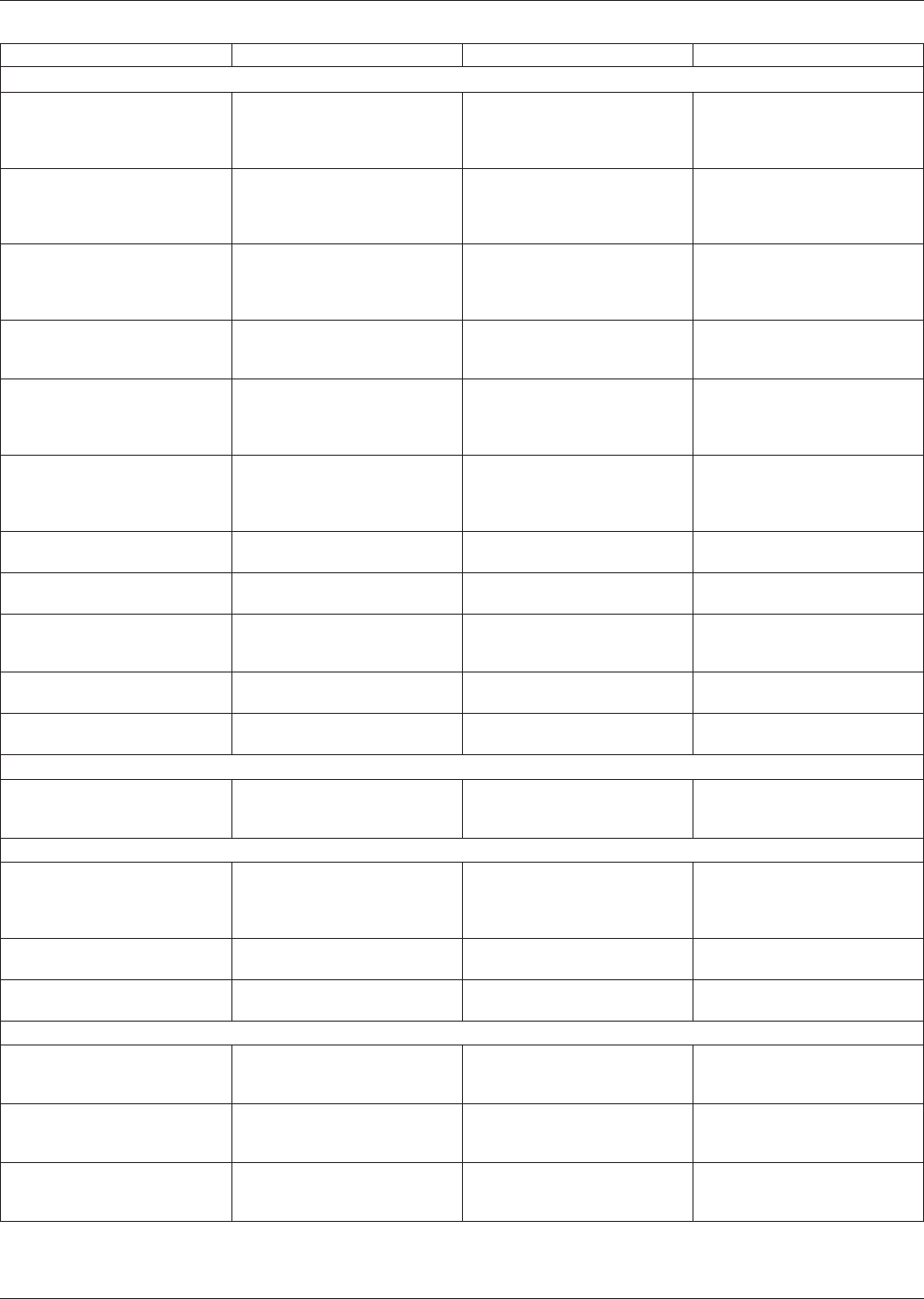
Table 4−1 Advantages and Disadvantages of Various Types of Substrates
TYPE MAJOR ADVANTAGES MAJOR DISADVANTAGES COMMENTS
ORGANIC BASE SUBSTRATE
Epoxy fiberglass Substrate size, weight; reworkable;
dielectric properties; conventional
board processing, availability,
cost/performance value.
Thermal conductivity x, y, and z axis CTE a concern for
high density applications.
Polyimide fiberglass Same as epoxy fiberglass plus
high temperature z axis CTE;
substrate size; weight; reworkable,
dielectric properties.
Thermal conductivity; moisture
absorption.
Same as epoxy fiberglass; x, y,
and z axis CTE a concern for high
density applications.
Epoxy aramid fiber Same as epoxy fiberglass; x-y axis
CTE; substrate size; lightest
weight; reworkable; dieletric
properties.
Thermal conductivity; resin
microcracking; z axis CTE; water
absorption; cost; resin adherence.
Volume fraction of fiber can be
controlled to tailor x-y CTE. Resin
selection critical to reducing resin
microcracks.
Polyimide aramid fiber Same as epoxy aramid fiber; z
axis CTE; substrate size; weight;
reworkable; dielecric properties.
Thermal conductivity; resin
microcracking; water absorption;
cost; resin adherence.
Same as epoxy aramid fiber.
Polyimide quartz (fused silica) Same as polyimide aramid fiber; x,
y, z axis CTE; substrate size;
weight; reworkable; dielectric
properties.
Thermal conductivity; drilling;
availability; cost; low resin content
required.
Volume fraction of fiber can be
controlled to tailor x-y CTE. Drill
wearout higher than with
fiberglass.
Fiberglass/Teflon laminates Dielectric constant; high
temperature stability; thermal
conductivity; x and y axis CTE.
Same as epoxy fiberglass; low
temperature stability; thermal
conductivity; x and y axis CTE;
difficult processing.
Suitable for high speed logic and
high frequency applications. Same
as epoxy fiberglass.
Flexible dielectric Lightweight; minimal concert to
CTE; configuration flexibility.
Size Rigid-flexible boards offer tradeoff
compromises.
Thermoplastic 3-D configurations; low
high-volume cost.
High injection molding setup costs;
additive processing.
Very limited applications.
Bismaleimide/triazine glass Improved dielectric properties;
multiple thermal shock; minimum
cost penalty for upgrade.
Thermal conductivity; x, y, and z
axis CTE.
Applicable to MCM-L technology.
Composite CEM-1 and CEM-3 Punchable at room temperature;
cost; stiff enough for SMD.
x and y axis CTE; thermal
conductivity.
Substrate of choice for consumer
products with SMDs.
Paper-based phenolic Punchable with heat; lowest cost. Single-sided only; stiffness;
availability; x and y axis CTE.
Majority of world market is
paper-based.
NONORGANIC BASE
Alumina (ceramic) CTE; thermal conductivity;
conventional thick film or thin film
processing; integrated resistors.
Substrate size; rework limitations;
weight; constant; brittle; dielectric
constant.
Most widely used for hybrid circuit
technology.
SUPPORTING PLANE
Printed board bonded to plane
support (metal or nonmetal)
Substrate size; reworkability;
dielectric properties; conventional
board processing x-y axis CTE;
stiffness; shielding; cooling.
Weight The thickness/CTE of the metal
core can be varied along with the
board thickness, to tailor the
overall CTE of the composite.
Sequential processed board with
supporting plane core
Same as board bonded to
supporting plane.
Weight Same as board bonded to
supporting plane.
Discrete wire High speed interconnections; good
thermal and electrical features.
Licensed process; requires special
equipment; cost; availability.
Same as board bonded to low
expansion metal support plane.
CONSTRAINING CORE
Printed board bonded with
constraining metal core
x and y axis CTE; uses FR-4 or
polyimide/glass materials.
Weight; internal layer registration;
delamination; via hole cracking, z
axis CTE.
Can be used as power/ground
planes.
Printed board bonded to low
expansion graphite fiber core
Same as board bonded to low
expansion metal cores; stiffness,
thermal conductivity; low weight.
Cost; microcracking; z axis CTE. The thickness of the graphite and
board can be varied to tailor the
overall CTE of the composite.
Compliant layer structures Substrate size; dielectric
properties; x-y axis CTE.
z axis CTE; thermal conductivity. Compliant layer absorbs difference
in CTE between ceramic package
and substrate.
IPC-D-279 July 1996
18