IPC-D-279 EN.pdf - 第82页
IPC-279-B3 Figure D−3 Use of Heat Slug July 1996 IPC-D-279 71
convection. For most products using low power devices,
strategic placement of a few ICs and careful venting in a
housing or enclosure is adequate. For the products used in
a friendly environment, such as the typical air conditioned
office, one board assembly will survive indefinitely. But as
the complexity and component density increases, creative
thermal management techniques must be adopted.
Transferring heat from the component body of ICs and
power regulators usually requires some form of physical
contact to a mass of material attached to the device. Using
hardware or thermally conductive adhesives, as shown in
Figure D-1 is a common practice for thermal management.
The thermal rise can be distributed to a larger surface area,
thereby keeping the component within a recommended
operating temperature range. The efficiency of this dissipa-
tion and distribution is reliant on the area of the heatsink
mass and the loss expected through the interface media.
When attachment hardware is used, a thermal compound is
applied to prevent air, moisture and contaminants from
forming between surfaces. When epoxy attachment is nec-
essary, a thermally conductive material is chosen. The most
efficient thermal conductive epoxy usually contains an
electrically conductive filler. When maximum insulation is
also critical, the heat transfer efficiency from the compo-
nent to the heatsink will be reduced. Researchers are work-
ing on new compounds each year to further improve these
thermal transfer characteristics, and heat transfer tech-
niques for through hole devices are as varied as the engi-
neer’s imagination.
Care must be taken that the thermal planes do not cause
tensile loading of the solder joints.
Typically signal layers on a printed board board are etched
in
1
⁄
2
ounce or 1 ounce copper clad dielectric. But 2 and 3
ounce copper is also available for use on power and ground
layers. Of course, if the heat transfer is a mechanical
attachment to the chassis, the ground plane or planes would
provide a thermal conduit to transfer the heat from the
component’s body into the internal copper layer of this
substrate. When specifying the copper thickness on each
side of one dielectric layer, the layers and copper thickness
should be distributed evenly as the example in Figure D-1.
A non-symmetrical lamination may warp excessively dur-
ing reflow solder process.
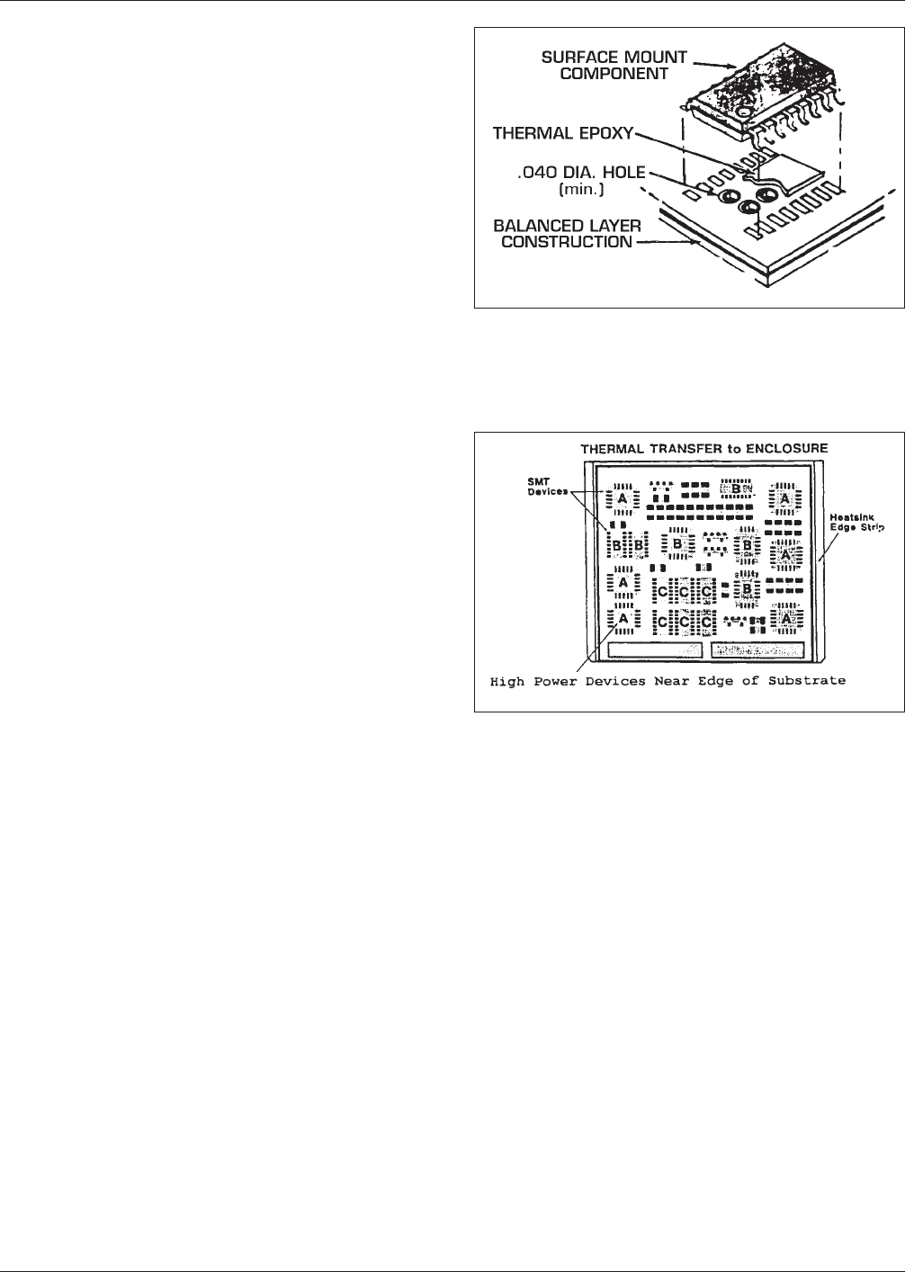
The thermal rise expected from the components must be
determined, and if this collective temperature rise is
beyond the recommended operating temperature limits of
the device; a careful evaluation of the component grouping
is in order. Distribution of higher power devices on the
outer edge of the substrate panels will provide the neces-
sary correction to control and distribute thermal rise away
from the components. The more direct the thermal path is
away from these components the better; don’t locate high
power devices in the center of the substrate. Rather, place
them closer to the heat transfer edge leaving low power
devices in the center area. See figure D-2.
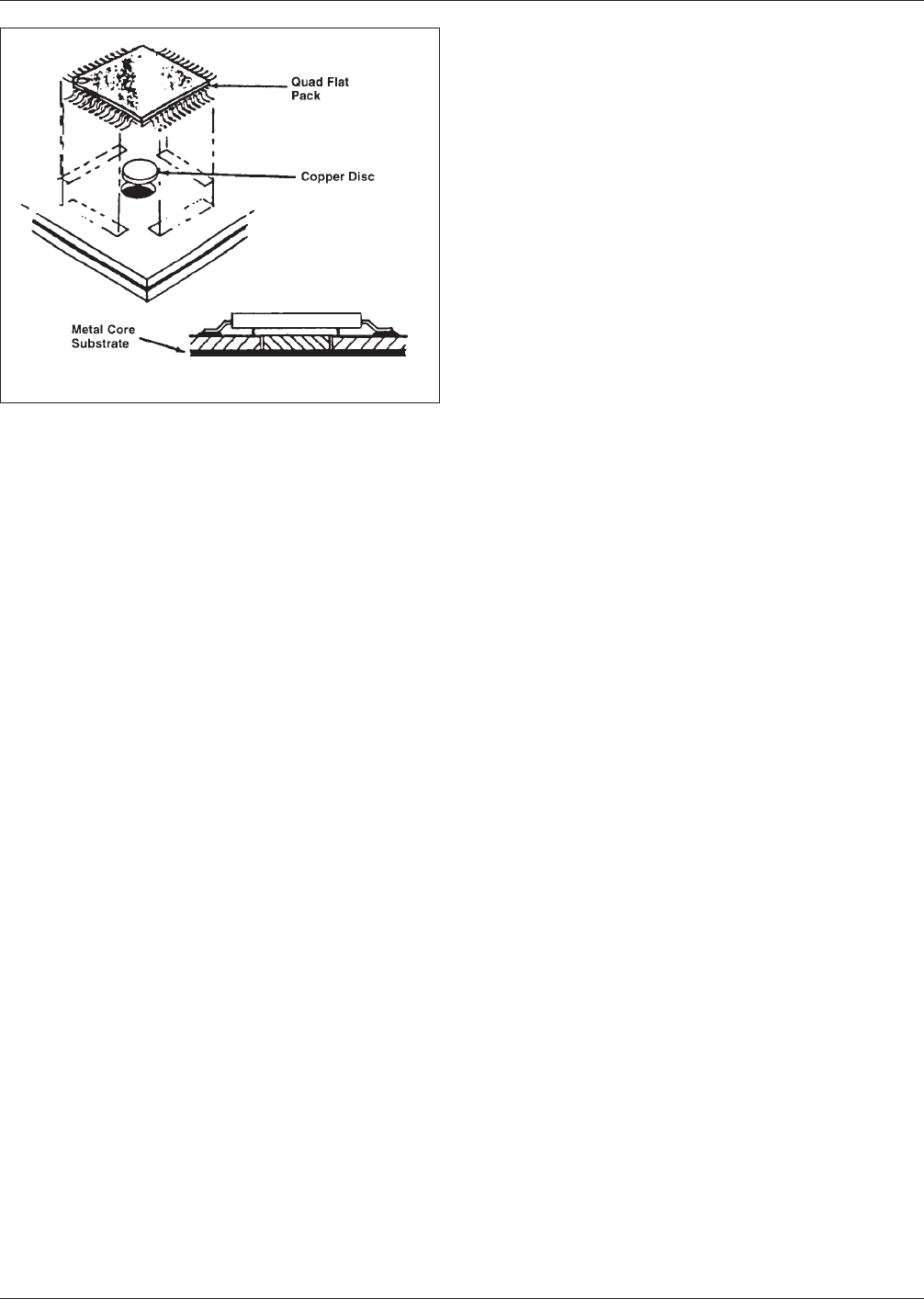
Figure D-3 describes techniques used to transfer thermal
rise of a SMT device through the outer dielectric layer of
the printed board to an internal ground plane of metal core.
Multilayer printed boards may have power and ground
planes internally layered and intermixed with signal layers.
This mass of copper planes can be an efficient thermal
conductor to transfer heat to the outer edge of the substrate
or the chassis.
IPC-279-D1
Figure D−1 Thermal Vias and Planes
IPC-279-B2
Figure D−2 Other Methods of Conductive Heat Transfer
IPC-D-279 July 1996
70
IPC-279-B3
Figure D−3 Use of Heat Slug
July 1996 IPC-D-279
71

Appendix E
Environmental Stresses
The printed board assembly starts its exposure to environ-
mental stresses during bare board fabrication, assembly and
repair/ rework before it even enters the service environ-
ment. These stresses can be thermal, chemical, mechanical
or electrical in nature. It is important to understand the
impact of environmental stresses to assure the reliability of
the assembly during its service life.
E-1.0 THERMAL
E-1.1 Effects of Rework and Repair
‘‘Touch up’’ is the
application of heat and solder to a solder joint which is
deemed cosmetically imperfect. Rework is the correction
of a defect before the SM PWA leaves the plant. Repair is
the correction of a defect found in the field. Information on
rework and repair may be found in IPC-R-700. Each cor-
rection requires the heating of one or more solder joints
above the liquidus temperature of lead-tin eutectic solder
(183°C), typically above 210°C, and may involve the
removal and replacement of a component. Note that this
temperature of 183°C is well above several critical tem-
peratures in a SM PWA.
E-1.2 Glass Transition Temperature for Printed Boards
The glass transition temperature (T
g
) of most epoxy-glass
boards is ~125°C. For multi-functional epoxy glass boards,
T
g
is ~160°C. T
g
is greater for polyimide glass printed
boards which have a T
g
of 250°C. There are many other
printed board materials that fall between these two
extremes. Exceeding the T
g
of the printed board results in
significant expansion of the printed board in the z axis,
hence in stresses in the barrels of plated through holes and
vias; the result can be intermittent or permanent opens. The
intermittent opens can generally be detected during tem-
perature changes of the PWA (see Appendix B).
Printed boards with a lower T
g
such as epoxy-glass boards
when heated locally, during component removal or compo-
nent replacement, to temperatures > T
g
, will tend to bulge
in the heated area. The solder joints of the replacement
component will be under tension and may fail when the
assembly cools down.
When using hot gas or IR systems to remove or replace
components, minimize printed board time at temperature.
During component removal, there should be no component
lifting or twisting during removal until solder is liquid on
all lands. This minimizes stress on the leads where they
enter the component package (with the result of cracked
plastic package body, damaged glass to metal seals), as
well as stress on the lands and their adhesive bond to the
printed board (with the result of lifted lands).
E-1.3 Intermetallic Compound Growth The copper in
the printed board conductors and component leads reacts
more rapidly with the tin in the solder to form a brittle
intermetallic compound (IMC) such as Cu
3
Sn and Cu
6
Sn
5
at higher temperatures. The original eutectic solder will be
transformed into a lead-rich layer. In the worst case, the
surface is exposed and oxidized; this lead oxide rendering
that surface unsolderable.
A solder joint kept at temperatures exceeding 150°C will
result in a lead-rich joint which is less ductile than one with
eutectic solder and the fatigue life of the joint will be
degraded. The IMC layer will tend to act as a shear plane
under overload conditions. These comments apply to
neighboring joints during component removal or replace-
ment and to ‘‘touch up’’ of a joint; some data indicate that
solder joints which undergo a ‘‘touch up’’ are less reliable.
If the molten lead is removed from the land by wiping, the
exposed IMC layers can rapidly oxidize and become unsol-
derable.
If the heat source is solder (wave or fountain), the interme-
tallics will be carried away and in the extreme, the copper
land will be dissolved.
When using hot gas or IR systems to remove or replace
components, keep the heat away from neighboring compo-
nents and joints. Hot air deflectors and IR shielding panels
may be required for component protection.
E-1.4 Glass Transition Temperature for Plastic Encap-
sulating
The T
g
range of most molding compounds used
in the plastic encapsulation of semiconductors and passive
networks is in the range of ~150°C to 180°C.
Exceeding the T
g
of the moulding compound of the com-
ponents during component removal results in internal
stresses to the metallization and passivation of the silicon
chip. This damage can hinder failure analysis of the
removed component and can also be suffered by a neigh-
boring component. Disruption of the metallization can
result in opens and dysfunction of the chip. Damage to the
passivation can result in long term corrosion of and opens
in the metal. Exceeding the T
g
can also cause delamination
of the molding compound from the surface of the silicon
chip or the surfaces of the leadframe; condensed moisture
can pool in the delaminated sites and lead to dendrites and
corrosion. Where the delamination coincides with bonding
pads and wire bonds, bond shear can occur.
When using hot gas or IR systems to remove or replace
components, if subsequent failure analysis is to be per-
formed on the removed component, dry the component
IPC-D-279 July 1996
72