IPC-D-279 EN.pdf - 第15页
IPC-279-02 Figure 1−2 Flow Chart for Reliability Assurance Processes ▼ ▼ ▼ ▼ ▼ ▼ ▼ ▼ ▼ ▼ ▼ ▼ ▼ ▼ ▼ ▼ ▼ ▼ ▼ ▼ ▼ ▼ ▼ ▼ ▼ ▼ ▼ ▼ Determine missing data. Is information complete enough for reliability analysis? Is reliability…
1.3.7 Testing Section 8.0 details the various testing
strategies, their purposes and their impact on reliability.
Also discussed are design for testability considerations.
Checklists for DfT from various sources are provided in
Appendix J.
1.4 Terms and Definitions Terms and definitions used
here are in accordance with IPC-T-50, and IPC-SM-785
except as otherwise specified.
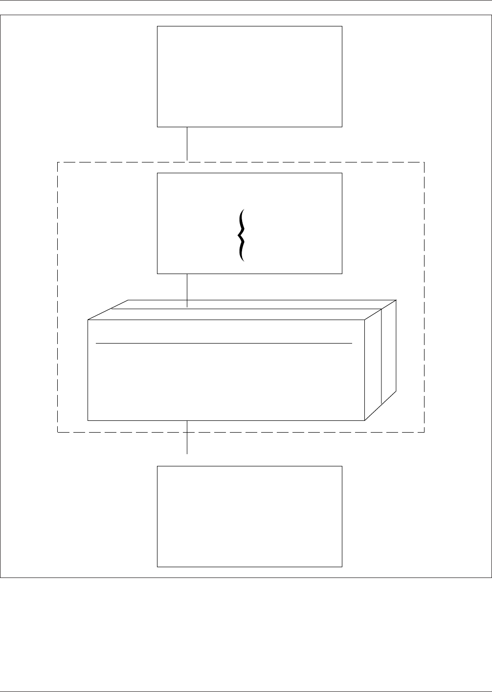
IPC-279-01
Figure 1−1 General Design Steps
▼
▼
▼
1. Years of Service
2. Acceptable Failure Rate Limit
3. Repair/Replacement Strategy
Identify Reliability Reqts.
Levels:
•
Component
•
Assembly
Identify Life Environment
Phases:
•
Storage
•
Transportation
•
Processing
•
Testing
•
Operating
Temp. Range
•
•
•
Vibration/Shock
Identify Storage Env.
Transp. Env.
Proc.
ESD
•
•
•
Atmosphere
Analyze & Select
•
Components
•
Materials
•
Assembly Processes
•
Test Strategy
•
Thermal Mgt. Strategy
•
Solder Attachments
•
PWB Design
July 1996 IPC-D-279
3
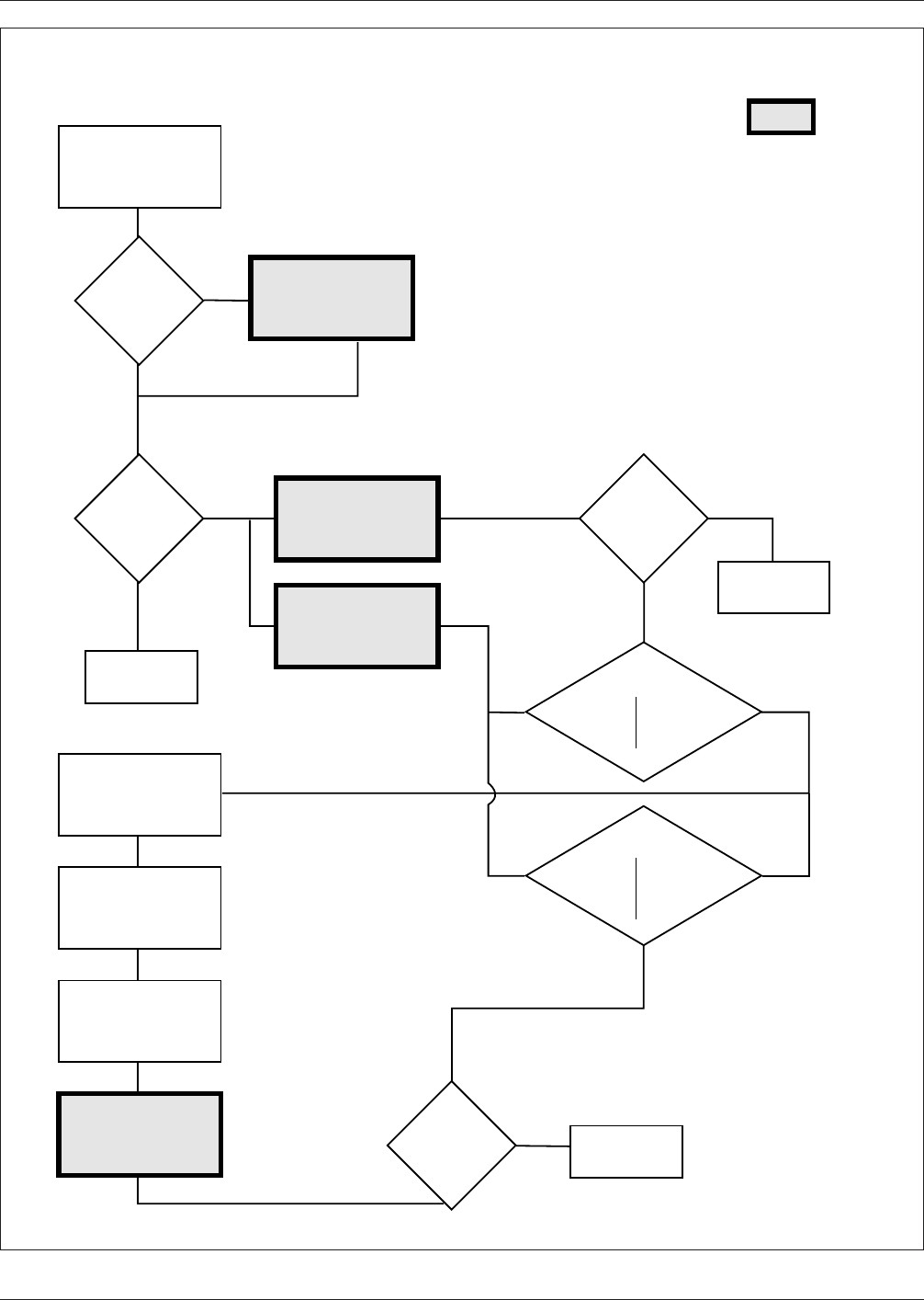
IPC-279-02
Figure 1−2 Flow Chart for Reliability Assurance Processes
▼
▼
▼
▼
▼
▼
▼
▼
▼
▼
▼
▼
▼
▼
▼
▼
▼
▼
▼
▼
▼
▼
▼
▼
▼
▼
▼
▼
Determine
missing
data.
Is
information
complete enough
for reliability
analysis?
Is
reliability in
Appendices
A, B & C
Estimate product
reliability
Appendices A, B & C
Redesign product.
Redefine
requirements.
Is
estimated
reliability
adequate?
Finish
Finish
Solution:
Redesign
Redefine
Reduce
Uncertainties
Solution:
Redesign
Redefine
Review test
program for
correct-
ness
Finish
Is
reliability
adequate
?
Collection of all
available inform-
ation & requirements
Flow Chart for Reliability Assurance Processes
Define proper
test, conditions,
IPC-SM-785
Accelerated
reliability
test(s)
Evaluate results
Failure Mode
Analysis
Estimate product
reliability from
test results
▼
Yes
No
Yes
Yes
No
No
Yes
No
Main Focus of Document
IPC-D-279 July 1996
4

2.0 APPLICABLE DOCUMENTS
The following documents of the issue in effect on the date
of issuance of this specification, form a part of this speci-
fication to the extent specified herein. Subsequent issues of,
or amendments to, these documents may become a part of
this specification.
2.1 Institute for Interconnecting and Packaging Elec-
tronic Circuits (IPC)
1
IPC-T-50 Terms and Definitions for Interconnecting and
Packaging Electronic Circuits
IPC-D-275 Design Standard for Rigid Printed Boards and
Rigid Printed Board Assemblies
IPC-TR-476 How to Prevent Electrically Induced Failures
(Electromigration) in Printed Wiring Board Assemblies
IPC-TM-650 Test Methods Manual
2.6.20 Assessment of Plastic Surface Mount Compo-
nents for Susceptibility to Moisture Induced Damage
IPC-ET-652 Guidelines and Requirements for Electrical
Testing of Unpopulated Printed Boards
IPC-PE-740 Troubleshooting guide for Printed Board
Manufacture and Assesmbly
IPC-SM-782 Surface Mount Design and Land Pattern
Standard
IPC-SM-785 Guidelines for Accelerated Surface Mount
Solder Attachment Reliability Testing
IPC-SM-786 Procedures for Characterizing and Handling
of Moisture/Reflow Sensitive ICs
IPC-SM-816 SMT Process Guideline and Checklist
2.2 Electronic Industries Association
2
EIA-541 Packaging Material Standards for ESD Sensitive
Items
EIA-583 Packaging Material Standards for Moisture Sen-
sitive Items
EIA-625 Requirements for Handling Electrostatic Dis-
charge Sensitive (ESD) Devices
JESD 22-A112 Moisture-Induced Stress Sensitivity for
Plastic Surface Mount Devices
JESD 22-A113 Preconditioning Procedures of Plastic Sur-
face Mount Devices Prior to Reliability Testing
JESD 42 Requirements for Handling Electrostatic-
Discharge Sensitive (ESDS) Devices
JEP113 Symbol and Labels for Moisture Sensitive
Devices
2.3 Joint Industry Standards
J-STD-001
Requirements for Soldered Electrical and Elec-
tronic Assemblies
J-STD-004 Requirements for Soldering Fluxes
3.0 DESIGN FOR RELIABILITY FOR SURFACE MOUNT
ASSEMBLIES
During the initial design stages of any project, a full
knowledge of the product requirements must be under-
stood. These requirements include the life cycle environ-
ment, printed board design constraints, thermal effects, ser-
viceability, and all aspects of reliability. This section
reviews these considerations and the effects caused by
each. The design details for DfR are discussed in Appendi-
ces A, B, and C.
3.1 Life Cycle Environment The environmental influ-
ences that determine the reliability of surface mount assem-
blies have to include all environments from manufacture to
the end of the design life. These life cycle environments
include manufacturing processes, burn-in and/or ESS pro-
cedures, transport, storage and use conditions.
Depending upon the product application, any of the life
cycle environment periods may have an overwhelming
effect on the product reliability. The effects of all these life
cycle environment periods can accumulate and need to be
summed together using the Palmgren-Miner’s rule. (See
Equations #9 through #11 in Appendix A)
3.1.1 Manufacturing Processes Many manufacturing
processes used in Surface Mount Assembly require changes
in temperature. The most severe of these are processes
requiring the melting of solder. These processes can affect
PTH and PTVs, solder attachments, components and
printed boards. Other processes include bake-out of printed
boards, curing of adhesives, and curing of polymeric coat-
ings.
3.1.2 Processing Temperature Excursions During pro-
cessing and assembly of electronic assemblies, temperature
excursions, particularly during solder reflow and repair,
cleaning, or imposed thermal cyclic testing, take place that
are damaging to some parts of the assemblies and consume
part of the available life. These thermal excursions can
cause fractures in the PTVs of the multilayer printed board.
1. IPC, 2215 Sanders Road, Northbrook, IL 60062-6135.
2. Electronic Industries Association, 2001 Eye Street, N.W., Washington, DC 20006.
July 1996 IPC-D-279
5