IPC-D-279 EN.pdf - 第62页
plating conditions. Under these conditions, in combination with the non-uniform plating current densities that also get worse with increasing aspect ratios, the copper deposit quality rapidly deteriorates with increasing…

Appendix B
Design for Reliability (DfR) of Plated-Through Via (PTV) Structures
B-1.0 PLATED-THROUGH VIA (PTV) RELIABILITY
ISSUES
Plated-through-holes (PTHs) serve to electrically connect
different conductor layers in multilayer printed circuit
boards (MLBs). In conventional interconnection technol-
ogy employing through-mounted components, the PTHs
also serve the function of providing a structure that accepts
the component leads and to which these leads can securely
be solder attached. This structure consisting of the copper
PTH barrel containing a component lead and filled with
solder provides a very robust, multiple-redundant electrical
and mechanical connection between the component and the
MLB.
The continuing drive towards higher functionality, higher
density, and lower weight was brought about and made
possible by the development of surface mounted technol-
ogy. This reduced the purpose of the previously multi-
functional PTHs to providing only the electrical intercon-
nections between the MLB layers; the diameters of PTHs
could also be reduced, since they no longer needed to be
large enough for the component lead insertion operation.
To distinguish the two types of PTHs, the PTHs without
component leads are frequently referred to as ‘PTH-vias’ or
PTVs. At the same time, the increased functionality and
density of the components often brought about a need to
increase the number of layers in MLBs, and thus to
increase the MLB thickness.
The decreasing PTV diameters, particularly in combination
with the increasing MLB thicknesses, make copper plating
into the PTVs more difficult. This problem was first recog-
nized during an IPC round robin study [Ref. B-7: 1], which
led to a more detailed round robin study specifically
focused on this issue [Ref. B-7: 2]. PTVs having a small
diameter—less than ~0.5 mm—and/or a high aspect ratio
of MLB thickness to drilled PTV diameter—more than
4—were found to require special treatment for adequate
reliability.
During this study the material properties, processing
parameters, and environmental test and use conditions
important for the reliability of PTVs were identified. The
results of these studies together with prior and subsequent
work [Refs. B-7: 3-9] has been utilized to develop a prac-
tical methodology to aid in the DfR of PTVs, as well as to
permit the assessment of the reliability of PTVs given the
assembly and test procedures and the use environments in
the field [Ref. B-7: 10].
In the IPC round robin test program [Ref. B-7: 1] the IEC
(Hot Oil Test, IEC 362-2) test—designed to simulate solder
reflow thermal shock cycles—was used to evaluate the reli-
ability of small-diameter PTVs. It was found that assembly
processes involving large temperature excursions constitute
a significant reliability threat due to low-cycle fatigue for
PTV copper barrels with low ductility or large stress con-
centrations. It was concluded that failures, to the extent
they occur at all, occur typically in the first 10 cycles due
to overstress crack initiation followed by crack propaga-
tion. This conclusion was reinforced by the findings of
Oien [Refs. B-7: 3, 4], which showed that crack initiation
typically occurs during the first or second cycle of over-
stress. Unless failure occurs within 10 cycles of the over-
stress loading typical of solder reflow, solder reflow over-
stressing is not a problem. Additional cycles will
eventually lead to fatigue-induced failures. The failures
that occurred in the IPC study were observed in product
from vendors rated ‘poor’ to ‘good’ on an arbitrarily sub-
jective scale with some consistency in differentiation. No
superior-rated vendor product failed, but it has to be noted
that the testing had an arbitrary cut-off. This led to the
definition of a numerical quality index that is now utilized
in an improved more detailed form in the reliability mod-
eling shown in Reference B-7:2 [Ref. B-7: 10].
During the product use, the severity of the thermal use
environment has a great impact on the reliability of the
PTVs. The ‘‘MIL-T’’ and ‘‘COM-T’’ thermal cycling tests
[Ref. B-7: 2] were designed to simulate severe and rela-
tively benign use environments, respectively. While fail-
ures in the ‘‘MIL-T’’ test occurred depending on the con-
struction of the MLBs and the quality of the PTVs, failures
did not occur as the result of the ‘‘COM-T’’ test. It needs
to be noted however, that the ‘‘MIL-T’’ and ‘‘COM-T’’
thermal cycling tests unfortunately had arbitrary test cut-
offs at 400 and 1000 cycles, respectively.
B-1.1 Copper Plating Process
B-1.1.1 Acid Copper Plating
One finding of the IPC
round robin study [Ref. B-7: 2] was that PTVs with aspect
ratios larger than three and plated with standard electrolytic
acid copper show decreasing thermal cyclic fatigue life. It
was found that the copper plating process window narrows
as the PTV aspect ratio increases and that the standard
electrolytic plating processes become inadequate even with
optimum process controls. These findings agree with ear-
lier studies investigating the effects of plating current den-
sity and agitation level on copper deposit quality in PTVs
[Ref. B-7: 5]. In this study it was shown that inadequate
electrolyte replacement rates, which can clearly occur in
high-aspect-ratio PTVs, will lead to mass-transport limited
IPC-D-279 July 1996
50

plating conditions. Under these conditions, in combination
with the non-uniform plating current densities that also get
worse with increasing aspect ratios, the copper deposit
quality rapidly deteriorates with increasing aspect ratios.
The resulting copper deposits within the PTV can have
significantly lower ductility and strength than the copper
deposits plated at the same time external to the PTVs, e.g.
on plating mandrels. The decline in physical properties is
frequently accompanied by increased ‘dog-boning’ and
nodule formation as well [Ref. B-7: 10].
The copper deposits from standard acid copper baths in
high-aspect-ratio PTVs, even with uniform plating in the
PTV barrels and good intrinsic tensile properties, as deter-
mined by testing foil specimens from flat plating mandrels,
perform only marginally in thermal cycling tests. For this
reason, special plating solutions have been developed, that
allow reduced plating current densities at the expense of
increased plating times, but producing significantly
improved PTV copper barrel reliability.
B-1.1.2 Pyrophosphate Copper Plating Pyrophosphate
plated copper was unfortunately not part of the IPC round
robin studies [Refs. B-7: 1, 2]. It has however been shown,
that pyrophosphate copper is less susceptible to the effects
of non-uniform plating current densities and higher PTV
aspect ratios.
B-1.2 Material Properties
B-1.2.1 Tensile Properties
The tensile properties of the
PTV copper deposits are very important, both for the per-
formance of the PTVs during subsequent processing and
use, and for the DfR for the PTVs. The properties that are
needed are: (1) the tensile strength, (2) the yield strength,
(3) the modulus of elasticity, (4) the modulus of plasticity,
and (5) the fracture ductility.
It has also been found, that the electrolytically plated cop-
per deposits have a modulus of elasticity significantly
below that of cast and rolled copper reported in material
property references. It therefore is necessary to measure the
modulus of elasticity, which can be done during the tests to
determine the yield and tensile strengths of the deposits.
The tensile strength, the yield strength, the modulus of
elasticity and the modulus of plasticity can be determined
from tensile tests. To properly determine the modulus of
elasticity, the ‘interrupted tensile test’ method should be
utilized.
It needs to be noted however, that these tensile properties
come from samples plated onto flat stainless steel mandrels
and only set the upper bounds for the strength and ductil-
ity of the copper deposit inside the PTV. The evidence is
circumstantial, but very strong, that these properties are
significantly degraded inside of high-aspect-ratio (board
thickness/PTV-diameter) PTVs [Ref. B-7: 2].
B-1.2.2 Ductility The tensile elongation is a very inaccu-
rate and subjective test for foil samples because of the
specimen geometry and the dependence on the test condi-
tions [Ref. B-7: 10, 11]. Tensile elongation for foil materi-
als is adequate for quality control and comparison pur-
poses, but it significantly underestimates the fracture
ductility of the material by about a factor of three (3) and
gives the false indication of a ductility dependence on foil
thickness.
It is for these reasons that the test cited in References
B-7:12 and 13, was developed. This test has a high dis-
crimination power in terms of quality variations of the cop-
per deposit, thus being very valuable as a process control
tool as well as providing direct input for the all-important
ductility of the copper deposit.
In order to assess the quality of the plated copper deposits,
foil samples plated onto mandrels need to be subjected to
fatigue ductility testing [Ref. B-7: 12].
It needs to be noted however, that this ductility comes from
samples plated onto flat stainless steel mandrels and only
set the upper bounds for the ductility of the copper deposit
inside the PTV. The evidence is circumstantial, but very
strong, that this property is significantly degraded inside of
high-aspect-ratio (board thickness/PTV-diameter) PTVs
[Ref. B-7: 2].
The ductility of the copper deposit in the PTV barrel can
be determined from the performance of the PTVs in accel-
erated testing resulting in low-cycle fatigue. In Table B-1
the results from two of the tests used in the Reference
B-7:2 applied to coupons from the same sample are given
together with the stresses and strain ranges resulting from
the thermal cycling/shock excursions. Also given is the
minimum ductility resulting from the first failures in the
tests using Eq. #1 in Section B-2.0 together with the initial
tensile strength.
The measured mandrel ductility was about 30%. Thus, the
ductility in the PTV barrels as given in Table B-1 indicates
a significantly lower deposit ductility as compared to the
ductility of the deposit on the MLB surface.
B-1.2.3 Fatigue Behavior It has been found that
annealed electrolytic acid copper strain-hardens upon the
application of cyclic strain loads during fatigue tests [Ref.
B-7: 11]. This results in high-cycle fatigue lives that are
longer than expected based on the initial material proper-
ties.
Conversely, annealed pyro-phosphate-plated copper strain-
softens as the result of the application of the cyclic strains
during the fatigue testing. Therefore, fatigue life tests in the
July 1996 IPC-D-279
51
high-cycle regime as per Reference B-7:12 need to be per-
formed in order to obtain an indication of the changes in
the material properties from either strain-hardening or soft-
ening during high-cycle fatigue. By using larger bend man-
drel diameters than are used for the fatigue ductility test,
the samples are subjected to high-cycle fatigue to assess
the material behavior of the copper plating under extended
fatigue loading.
B-1.3 Damage Mechanisms and Failure
B-1.3.1 PTV Quality
The quality of the PTVs, together
with the severity of the thermal expansion loading, is the
critical aspect in the reliability of PTVs.
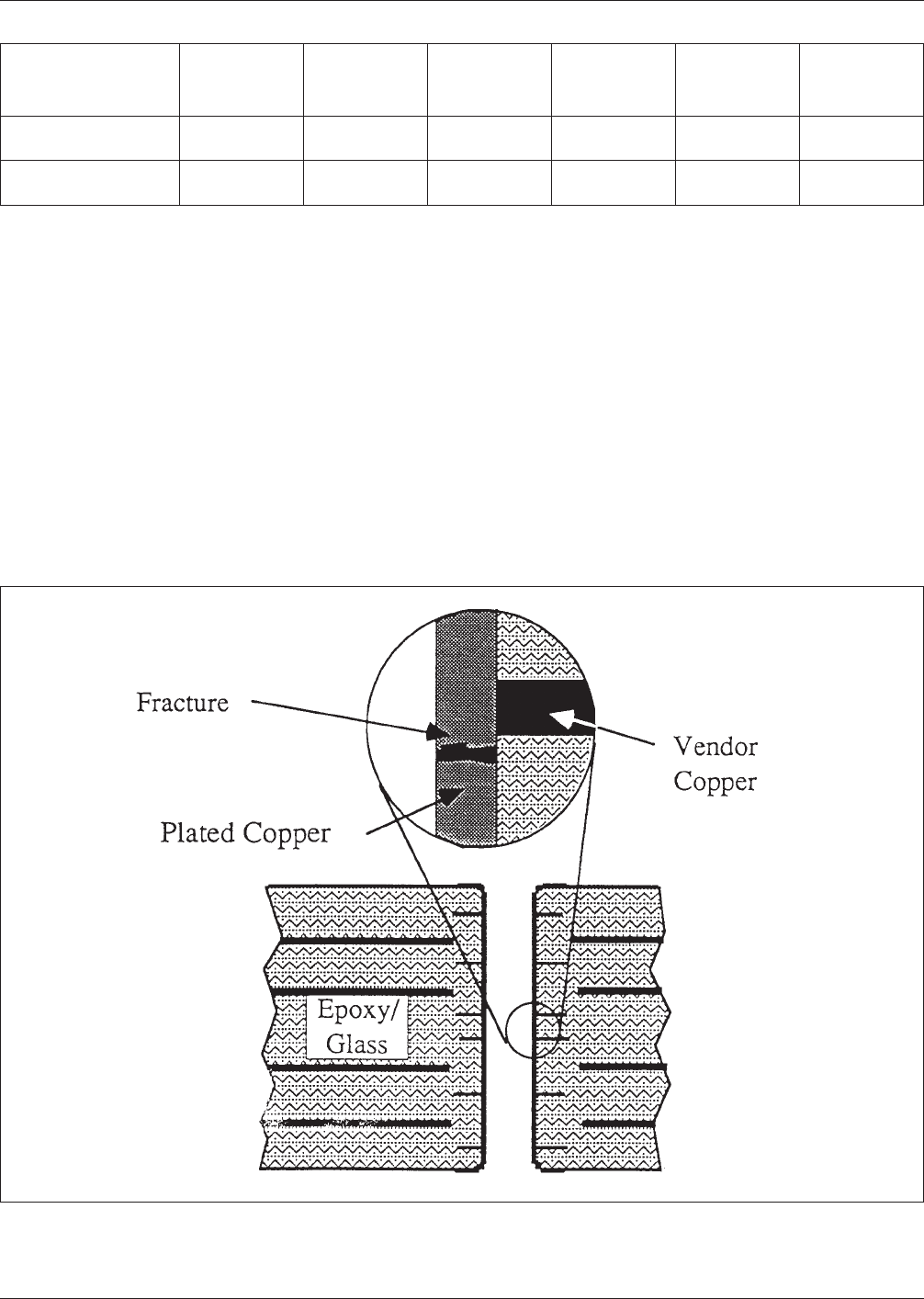
Even good quality PTVs will eventually fail and will typi-
cally do so as the result of a PTV barrel fracture near the
center of the barrel as is illustrated in Fig. B-1.
PTV failures can also occur as the result of PTV shoulder
fractures (see Fig. B-2) and internal land fractures. Failures
of these types typically are the consequence of an inad-
equate material choice for the vendor copper foils [Ref.
B-7: 14] used for the laminates or some processing error.
Of the ∆T≈180°C thermal excursion during the soldering
process, ∆T≈100°C is below T
g
at a mismatch in the
Table B-1 Estimates of Tensile Properties of Copper Deposit Inside the PTVs [Reference B-7:10]
Test
∆T
[°C]
Fatigue Life
N
f
[cycles]
Barrel Stress
σ
[MPa/ksi]
Strain Range
∆ε
max
(eff)
[%]
Copper
Strength
S
u
[MPa/ksi]
Minimum
Ductility
D
f
[%]
IEC Hot Oil
Thermal Shock
235 32 219/31.8 4.5 281/40.7 20.6
Temperature
Cycle/Shock
190 150 177/25.7 2.2 281/40.7 23.3
Figure B−1 Cross-Section Schematic of a PTV With a Barrel Fracture Near the Center of the MLB
IPC-D-279 July 1996
52