IPC-D-279 EN.pdf - 第69页
Interconnecting and Packaging Electronic Circuits, Northbrook, IL, September 1984. 2. ‘ ‘Round Robin Reliability Evaluation of Small Diam- eter Plated Through Holes in Printed W iring Boards,’ ’ IPC T echnical Report IPC…
reliability of these PTVs significantly. Therefore, it is best
to avoid the possibility of these stress concentrations all
together by tenting the PTVs. However, it needs to be
emphasized, that this issue is important only for severe use
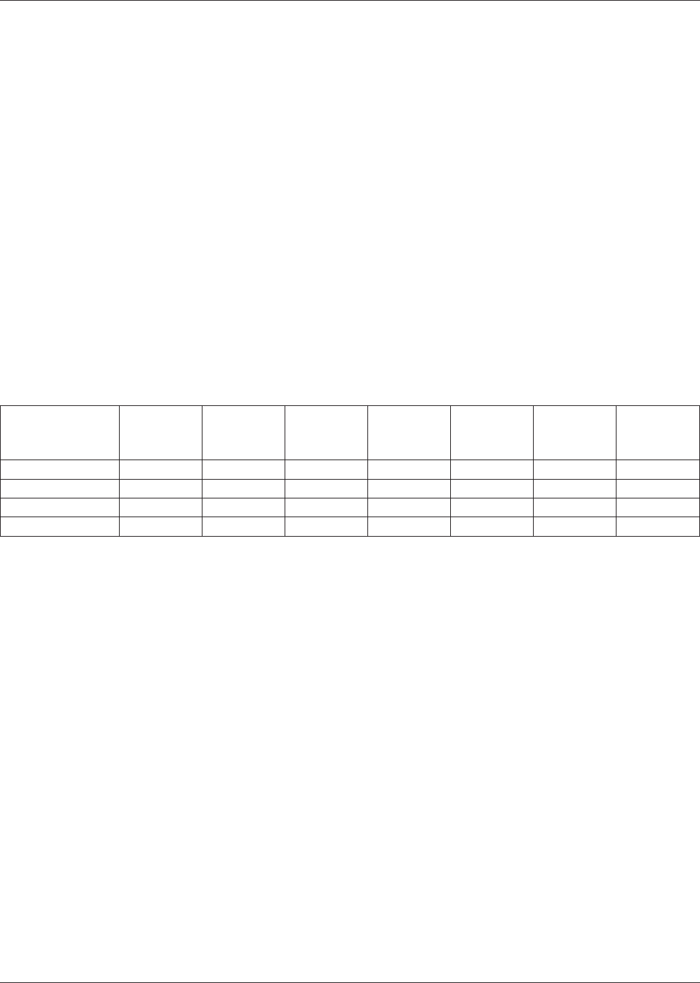
conditions with temperature cycles of about ∆T≥50°C, as
can be seen in Table B-2.
In Table B-1 in Section B-1.2.2 the minimum fatigue duc-
tilities resulting from two accelerated fatigue tests of PTVs
in MLBs are given. These estimates of the copper deposit
properties in the PTV barrels are used in Table B-2 to esti-
mate the minimum fatigue lives for a number of typical
electronic use environments. The fatigue lives are given
together with the pertinent information on the use condi-
tions and the resulting stresses and strains.
The results in Table B-2 indicate that the PTVs of good
quality do not constitute a reliability threat to most product
applications in the field. Only for the more severe use envi-
ronments would premature failures be anticipated. How-
ever, the results in Table B-2 would change drastically for
PTVs of low quality.
The DfR-process needs to emphasize a physics-of-failure
approach. The process might involve the following steps:
A. Identify Reliability Requirements—
expected design life and acceptable cumulative fail-
ure probability at the end of this design life;
B. Identify Loading Conditions—
use environments (e.g., IPC-SM-785) and thermal
gradients due to power dissipation;
C. Identify/Select Assembly Architecture—
substrate selections, material properties (e.g., CTE),
PTV diameter, aspect ratio;
D. Assess Reliability—
determine reliability potential of the designed assem-
bly and compare to the reliability requirements using
the approach shown here; this process may be itera-
tive;
E. Balance Performance, Cost and Reliability Require-
ments.
B-4.0 CRITICAL FACTORS FOR EMERGING ADVANCED
TECHNOLOGIES
The emerging advanced technologies are characterized by
denser packaging resulting in ever smaller structures. Thus,
the temptation exists to drive the PTV diameters ever
smaller and the aspect ratios higher. The DfR principles
detailed in Section B-3.0 need to be kept in mind in the
design and application of these emerging technologies.
B-5.0 VALIDATION AND QUALIFICATION TESTS
Validation and qualification tests have not been established
for PTVs. However, the test procedures used in the IPC
round robin program reported in IPC-TR-579, Round
Robin Reliability Evaluation of Small Diameter Plated
Through Holes in Printed Wiring Boards [Ref. B-7: 2],
could be utilized for this purpose.
Efforts are underway within the IPC via a round robin test
program to establish both qualitative and quantitative cor-
relation for a number of promising test methods.
B-6.0 SCREENING PROCEDURES
The crucial task is the elimination of the MLBs with thin-
plated PTVs without significantly affecting the remainder
of the MLBs. The fact that the defects not only involve
very thin plating (<10 µm), but occur in conjunction with
substantial stress/strain concentrations, makes this task pos-
sible.
An Environmental Stress Screening (ESS) could employ
the same test setup as the Hot Oil Test (IEC Specification
362-2, Test C) [Ref. B-7: 2], for three (3) to five (5) cycles.
Thus, together with the solder reflow operations necessary
for production, the MLBs would experience between eight
(8) to ten (10) such temperature excursions.
Given the result, based on standard IEC test criteria, that
the life under these loading conditions is 32 cycles, this
would consume between 25 and 30 % of the MLBs lives.
Considering the results in Table B-2, that still would leave
adequate life for most use environments.
B-7.0 REFERENCES
1. ‘‘Leading Edge Manufacturing Technology Report,’’
IPC Technical Report IPC-TR-578, The Institute for
Table B−2 Estimates of the Fatigue Life and Time to Failure of PTVs in Some Typical Use Environments from Table A-1
Used
Environment
∆T
[°C]
Estimated
Maximum
Annual
Cycles
Barrel Stress
σ
[MPa/ksi]
Strain Range
∆ε
[%]
Effective
Strain Range
∆ε
max
(eff)
[%]
Minimum
Fatigue Life
[cycles]
Estimated
Time to First
Failure
[years]
Computers 20 1460 67/9.7 0.08 0.20 8.0X10
6
5 500
Telecomm 35 365 117/16.9 0.14 0.35 75 000 205
Industrial 60 250 173/25.1 0.28 0.71 2 900 12
Automotive 80 365 174/25.2 0.38 0.95 1 200 3.3
July 1996 IPC-D-279
57

Interconnecting and Packaging Electronic Circuits,
Northbrook, IL, September 1984.
2. ‘‘Round Robin Reliability Evaluation of Small Diam-
eter Plated Through Holes in Printed Wiring Boards,’’
IPC Technical Report IPC-TR-579, The Institute for
Interconnecting and Packaging Electronic Circuits,
Northbrook, IL, September 1988.
3. Oien, M. A., ‘‘A Simple Model for the Thermo-
Mechanical Deformations of Plated-Through-Holes in
Multilayer Printed Wiring Boards,’’ Proc. 14th Ann.
IEEE Reliability Physics Symp. pp. 121-128, 1976.
4. Oien, M. A., ‘‘Methods of Evaluating Plated-Through-
Hole Reliability,’’ Proc. 14th Ann. IEEE Reliability
Physics Symp., pp. 129-131, 1976.
5. Engelmaier, W., and T. Kessler, ‘‘Investigation of Agi-
tation Effects on Electroplated Copper in Multilayer
Board Plated-Through Holes in a Forced-Flow Plating
Cell,’’ J. Electrochemical Soc., Vol. 125, No. 1, Janu-
ary 1978, pp. 3643.
6. Mirman, B. A., ‘‘Mathematical Model of a Plated-
Through Hole Under a Load Induced by Thermal Mis-
match,’’ IEEE Trans. Comp., Hybrid, Manuf, Technol-
ogy, Vol. 11, No. 4, December 1988, pp. 506-511.
7. Iannuzzelli, R., ‘‘Predicting Plated-Through-Hole Reli-
ability in High Temperature Manufacturing Pro-
cesses,’’ IPC Annual Meeting, Boston, MA, April
1990.
8. Ozmat, B., H. Walker, and M. Elkins, ‘‘A Nonlinear
Thermal Stress Analysis of the Plated Through Holes
of Printed Wiring Boards,’’ Proc. Int. Electronic Pack-
aging Conf. (IEPS). Marlborough, MA, September
1990.
9. Bhandarkar, S. M., A. Dasgupta, D. Barker, M. Pecht,
and W. Engelmaier,‘‘Influence of Selected Design
Variables on Thermo-Mechanical Stress Distributions
in Plated-Through-Hole Structures,’’ ASME J.Elec-
tronic packaging, Vol. 114, No. 1, March 1992, pp.
8-13.
10. Engelmaier, W., ‘‘Manufacturing and Reliability Issues
of Small Diameter/High-Aspect-Ratio Plated-Through-
Holes and Vias,’’Workshop Notes, Engelmaier Associ-
ates, Inc., 1991.
11. Engelmaier, W., ‘‘Results of IPC Copper Foil Ductility
Round Robin Study,’’ IPC Technical Report IPC-TR-
484, The Institute for Interconnecting and Packaging
Electronic Circuits, Lincolnwood, IL, April 1986.
12. ‘‘Flexural Fatigue and Ductility, Foil,’’ Test Method
2.4.2.1, Test Methods Manual IPC-TM-650, The Insti-
tute for Interconnecting and Packaging Electronic Cir-
cuits, Northbrook, IL.
13. ‘‘Standard Test Method for Ductility Testing of Metal-
lic Foil,’’ ASTM E 796-88, Annual Book of ASTM
Standards, ASTM, Philadelphia, PA.
14. ANSI/IPC-MF-150F, ‘‘Metal Foil for Printed Wiring
Applications,’’ The Institute for Interconnecting and
Packaging Electronic Circuits, Lincolnwood, IL, Octo-
ber 1991.
15. Cygon, M., ‘‘High Performance Materials for PCBs,’’
Circuit World, Vol. 19. No. 1, October 1992, pp. 14-18.
16. Olson, L.D., ‘‘Printed Wiring Boards: Conventional
Plastic Composite Boards’ Resins and Reinforce-
ments,’’ chapter in Electronics Materials Handbook,
Vol. I Packaging, ASM International, Materials Park,
Ohio, 1989, pp. 534-537.
17. Ozawa, S., T. Takeda and T. Ohtori, ‘‘Epoxy Resin
Multilayer Materials,’’ Proc. Printed Circuit World
Cony. VI, San Francisco, May 1993, pp. T5/1-T5/9.
18. Davis, B., ‘‘A Tour Through the Board Manufacturing
Process,’’ Printed Circuit Design. Vol. 10, No. 8,
August 1993, pp. 11-14.
19. Lampe, J. W., ‘‘The Interrelationships of Design,
Materials, and Processes for Surface Mount Assem-
blies in Military Applications,’’ Surface Mount Tech-
nology. Vol. 3, No. 7, November 1989, pp. 22-27.
20. Hu, M., ‘‘Choosing Laminates,’’ Advanced Packaging,
Vol. 2, No. 5, Fall 1993, pp. 16-18.
21. Engelmaier, W., ‘‘A New Ductility and Flexural
Fatigue Test Method for Copper Foil and Flexible
Printed Wiring,’’ IPC Technical Paper IPC-TP-204,
The Institute for Interconnecting and Packaging Elec-
tronic Circuits, Lincolnwood, IL, April 1978.
22. Engelmaier, W., ‘‘A Method for the Determination of
Ductility for Thin Metallic Materials,’’ Formability of
Metallic Materials-2000 A.D., ASTM STP 753, J. R.
Newby and B. A. Niemeier, eds., American Society for
Testing and Materials, 1982, pp. 279-295.
23. Manson, S.S., Thermal Stress and Low Cycle Fatigue,
McGraw-Hill, New York, 1966.
24. Engelmaier, W., ‘‘Designing Flex Circuits for
Improved Flex Life,’’ Proc 12th Electrical/Electronics
Insulation Conf., Boston, MA, November 1975.
25. Engelmaier, W., ‘‘Flexibility Considerations in the
Design of Flexible Printed Wiring,’’ Section 6.2.1.2,
IPC Printed Wiring Design Guide IPC-D-330, The
Institute for Interconnecting and Packaging Electronic
Circuits, Lincolnwood, IL, January 1982.
IPC-D-279 July 1996
58

Appendix C
Design for Reliability (DfR) of Insulation Resistance
C-1.0 INSULATION RESISTANCE DAMAGE MECHA-
NISMS AND FAILURE
The damage mechanisms work generally in two distinct
regions: at the surface and in the bulk of the electronic
assemblies, particularly the printed board. It has been
reported, that surface and bulk phenomena exhibit different
time constants in the response to temperature changes [Ref.
C-7: 1]. The insulation resistance for a sample circuit is the
measured integrated effect of both surface and volume
resistivity as defined by ASTM [Ref. C-7: 2]. The mea-
sured bulk resistance will depend upon the nature of the
laminate, solder mask and/or conformal coating under
investigation. It will also depend upon the degree of cure
of the polymers and for printed boards on the quality of the
drilling process for the plated-through holes (PTHs) and
vias (PTVs), and will be affected by soldering flux/paste
residues if they dissolve into the polymeric material during
the soldering and/or cleaning processes.
Insulation resistance measurements provide important data
in the characterization of printed board laminates, multi-
layer boards (MLBs), soldering fluxes, solder masks, and
conformal coatings. Such measurements have been used to
study the effect of aging at accelerated conditions (tem-
perature, humidity and/or bias voltage) to determine any
detrimental effects on the reliability of the product.
Ohm’s law states that the magnitude of the current, I, flow-
ing through a circuit with a given resistance, R, is a linear
function of the applied voltage, V, such that
V = IR (Eq. C-1)
The resistance is an extrinsic property of the material
sample dependent on the resistivity of the material and the
geometry of the sample. The resistivity, ρ, of a material is
an intrinsic material property. The resistivity is determined
from the length, l, of the sample and its cross-sectional
area, A, and is related to R by
ρ=R
A
l
(Eq. C-2)
Resistivity that measures the resistance to current flow
through the bulk of a sample it termed volume resistivity,
ρ
v
,
ρ
v
= R
A
t
(Eq. C-3)
where t = the thickness of the bulk sample.
Surface resistivity, ρ
s
, measures the ability of an insulator
to resist the flow of current on its surface, such that
ρ
s
= R
A
s
l
(Eq. C-4)
where A
s
= the surface area and l is the length of the insu-
lating strip.
C-1.1 Surface Insulation Resistance (SIR) Surface insu-
lation resistance (SIR) measurements will depend on the
nature of the surface contamination and the amount of
moisture present during the measurement. Although SIR
readings are a combination of both bulk and surface resis-
tance, 99.9 % of the current leakage for FR-4 epoxy/glass
laminate will occur on the surface of the laminate, since the
ratio of the surface resistivity to the volume resistivity is
1:1000 [Ref. C-7: 3]. Test patterns for measuring volume
resistance will either use electrodes on the top and bottom
of the substrate (for z-axis measurements) or PTVs to PTV-
patterns for measuring the x, y-resistance. SIR patterns are
typically interdigitated comb patterns such as the IPC-B-24
coupon.
Some materials, notably polyglycol, act to reduce insula-
tion resistance by absorbing water and/or forming a mono-
layer of water at lower than saturation humidity, e.g. 75%
RH [Ref. C-7:4]
C-1.2 Electrochemical Corrosion Electrochemical cor-
rosion of metallic conductors and the migration of metal
ions between anode and cathode on a printed board can
lead to circuit failure. It is important to understand the
cause of these failures in order to select materials and pro-
cesses for printed board manufacture, soldering, and clean-
ing which will minimize the occurrence of these failures.
The tendency of the metal conductor to migrate under a
bias voltage in humid conditions has been shown to
decrease across the following series of metals [Ref. C-7: 5]
Ag >Pb>Solder>Cu (Eq. C-5)
Those metals whose hydroxides are more soluble at pH 7-9
have a higher migration rate. This is related to the pH gra-
dient between the anode and cathode when a film of mois-
ture is present.
In the case of SIR testing, the cathode is connected to the
high voltage source while the anode is connected to
ground. For electrochemical migration to occur, the path-
way must exist for ions to move from the anode to the
cathode. In the presence of moisture, the following electro-
chemical reactions can occur at the anode
H
2
O →
1
2
O
2
+2e
−
Cu → Cu
+1
+e
−
Cu → Cu
+2
+2e
−
Pb → Pb
+2
+2e
−
Sn → Sn
+2
+2e
−
Sn → Sn
+4
+4e
−
(Eq. C-6)
July 1996 IPC-D-279
59