IPC-D-279 EN.pdf - 第51页
where L is the wetted length of the solder joint. In addition, besides substantial shear stresses at the interface between the solder joint and the base material to which it is wetted, even lar ger peeling stresses occur…
−20°C to +20°C, in which the change from stress- to
strain-driven solder response takes place, do not follow the
damage mechanism described in Eqs. #1 and #2 [Ref. A-9:
34]. The damage mechanism is different than for more
typical use conditions and is likely dependent on a combi-
nation of creep-fatigue, causing early micro-crack forma-
tion, and stress concentrations at these micro-cracks caus-
ing faster crack propagation during the high stress cold
temperature excursions, as well as recrystallisation consid-
erations.
A-3.5 CAVEAT 3 — High-Frequency/Low-Temperatures
For high-frequency applications, f>0.5 Hz or t
D
<l s, e.g.,
vibration, and/or low temperature applications, T
C
< 0°C,
for which the stress relaxation and creep in the solder joint
is not the dominant mechanism, the direct application of
the Coffin-Manson [Ref. A-9: 14] fatigue relationship
might be more appropriate. This relationship is
N
f
(50%)=
1
2
[
2e
f’
∆γ
p
]
−1
c
[Eq. A-5]
where ∆γ
p
is the cyclic plastic strain range and c ≈ −0.6.
It has to be noted, that the determination of ∆γ
p
depends on
the expansion mismatch displacements and the separation
of the plastic from the elastic strains.
For loading conditions of this character, it is possible that
high-cycle fatigue behavior may be observed.
A-3.6 CAVEAT 4 — Local Expansion Mismatch
For applications for which the global thermal expansion
mismatch is very small, e.g. ceramic-on-ceramic or silicon-
on-silicon (flip-chip solder joints), the local thermal expan-
sion mismatch becomes the primary cause of fatigue dam-
age. Equation A-4 does not address the local thermal
expansion mismatch. This reliability problem needs to be
assessed using an interfacial stress analysis [Ref. A-9: 35]
and appropriate accelerated testing.
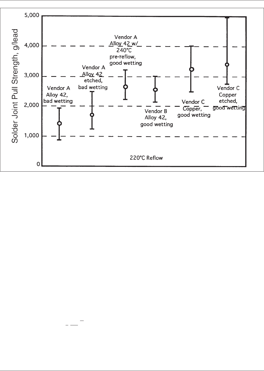
For leaded surface mount components with lead materials
that have CTEs significantly lower than copper alloy mate-
rials, e.g., Kovar
TM
or Alloy 42, the results from Eqs. A-1
and A-2 will be optimistic, since the fatigue damage con-
tributions from the solder/lead material CTE-mismatch, the
local thermal expansion mismatch, are not included.
It has shown that the interfacial stresses resulting from the
local expansion mismatch follow [Ref. A-9: 35].
τ∝L (α
Solder
−α
Basr
)(T
max
− T
min
)
[Eq. A-6]
Figure A−2 Solder Joint Pull Strengths for Gullwing Leads Consisting of Alloy 42 from Different Vendors and Copper
[Ref. A-9: 31]
July 1996 IPC-D-279
39
where L is the wetted length of the solder joint. In addition,
besides substantial shear stresses at the interface between
the solder joint and the base material to which it is wetted,
even larger peeling stresses occur. Both of these stresses
are proportional to the parameters given in Eq. A-6.
From Eq. A-6 it is quite clear, that for leads consisting of
Alloy 42, the wetted length of the solder joint, that is the
length of the lead foot should be minimized to reduce inter-
facial stresses. That, of course, is contrary to the good
practice that the foot length should be at least three times
the lead width for optimum solder joint quality. However,
since in most applications, the local expansion mismatch
results in contributory damage to the more important dam-
age caused by the global expansion mismatch, this contra-
indication can be ignored without suffering catastrophic
consequences.
From the available experimental data, the damage term, to
be used in Eq. A-1, for the local expansion mismatch alone
is
∆D(local)=
[
L∆α∆T
L
0
]
[Eq. A-7]
where the parameters are the same as in Eq. A-6 and
L
0
=0.1 mm, a scaling wetted length. The local expansion
mismatch is then treated as an additional loading condition
(see sections A-3.9 & A-3.10).
A.3.7 CAVEAT 5 — Very Stiff Leads/Very Large Expan-
sion Mismatches
Equations A-3 and A-4 differentiate between surface mount
solder attachments that are leadless and those with compli-
ant leads. Leadless solder attachments presume substantial
plastic strains due to yielding prior to creep and stress
relaxation, whereas Eq. A-4 assumes that the compliant
leads prevent stresses in the solder joints to reach levels
where substantial yielding, and thus plastic strains prior to
creep and stress relaxation, can take place.
However, there is an intermediate region that is not cov-
ered by these assumptions. For very stiff, non-compliant
leads (e.g., SM connector headers), perhaps at lead stiff-
nesses K
D
> ~90 N/mm and/or for very large thermal
expansion mismatches (e.g., ceramic MCMs on FR-4)
resulting in strain ranges ∆γ > ~10%, the damage estimates
in Eq. A-4 can be substantially in error, because the
assumptions underlying Eq. A-4 are violated.
For very stiff leads the stresses calculated in Eq. A-4 can
exceed the yield strength of the solder. Since yielding will
not permit stresses significantly higher than the yield
strength, these calculated stress ranges will overestimate
the cyclic fatigue damage and thus result in substantially
underpredicted fatigue lives. To prevent this analytical
error, the stress range in Eq. A-4 needs to be bounded by
the yield strength of solder in shear.
For very large thermal expansion mismatches the full dis-
placements will not be transmitted to the solder joints,
because the leads will accommodate displacements by plas-
tic deformations of the lead material. Possible exceptions
are situations where very stiff leads are also involved, in
which case the solder joint reliability is best estimated
using Eq. A-1 for leadless solder attachments. The strain
range that can be accommodated by creep and stress relax-
ation in the solder joints can be significantly exceeded by
the displacements resulting from very large thermal expan-
sion mismatches and the cyclic fatigue damage would be
significantly overestimated. Under these conditions FEA is
required to determine the split in the accommodation of the
displacements between the lead and the solder joints.
Under these circumstances, Eqs. A-3 and A-4 will provide
lower and upper bounds for the reliability estimates,
respectively. The higher the lead stiffness, the closer the
expected results will be towards the results given by Eq.
A-3 for the leadless—‘infinitely stiff leads’—solder attach-
ments. Very high lead stiffnesses can occur in the case of
through-hole component leads converted to surface mount
and for connector headers where the male header pins have
been simply bent into a gull-wing lead foot without any
reduction in the lead cross-section. Very high thermal
expansion mismatches occur primarily in accelerated test-
ing and in extraordinary environments like storage and
transport for products that are designed for benign operat-
ing environments.
A.3.8 Statistical Failure Distribution and Failure Prob-
ability
While the physical parameters define the median cyclic
fatigue life from physics-of-failure considerations, solder
attachment failures for a group of identical components
will follow a distribution—like all fatigue results—which
typically is best described by a Weibull statistical distribu-
tion [Ref. A-9: 36]. Given the statistical distribution, the
fatigue life at any given failure probability for the solder
attachment of a component can be predicted as long as the
slope of the Weibull distribution is known. Thus, the
fatigue life of surface mount solder attachments at a given
acceptable cumulative failure probability per component, x,
is —assuming a two-parameter (2P) Weibull statistical
distribution—given by
N
f
(x%)=N
f
(50%)
[
1n(1 − 0.01x)
1n(0.5)
]
1
β
[Eq. A-8]
where β = Weibull shape parameter or slope of the
Weibull probability plot; typically β≈3 for
fatigue tests, from low-acceleration tests of
stiff leadless solder attachments β≈4 and ≈2
for compliant leaded attachments.
IPC-D-279 July 1996
40

Experimentally, β can be found to be quite variable with
more severely accelerated reliability tests resulting in
tighter failure distributions and thus giving larger values
for β. Values of β in the range of 1.8 to 9.0 have been
observed.
There is some, unfortunately as yet inadequate, evidence
that for lower failure probabilities a three-parameter (3P)
Weibull distribution, postulating a failure-free period prior
to first failure [Refs. A-9: 32,37], may be applicable. From
physics-of-failure and damage mechanism considerations, a
failure threshold as provided by a 3P-Weibull distribution
makes sense, since the fatigue damage in the solder joints
has to accumulate to crack initiation and complete crack
propagation. While the 2P-Weibull distribution may be
overly conservative for designs to very small acceptable
failure probabilities (x < ~0.1%), a too liberal choice of the
failure-free period is definitely non-conservative. This area
requires more work.
Also, when designing to low failure probabilities, the vari-
ability in the quality of the solder joints may no longer be
negligible; also solder joints with latent defects that made
it into the field will have in impact on the actual failure
experience of a product in the field.
A-3.9 Multiple Cyclic Load Histories
The loading histories over the life of a product frequently
include many different use environments and loading con-
ditions [Refs. A-9: 38,39]. Multiple cyclic load histories
(e.g., ‘‘Cold’’ temperature fatigue cycles combined with
higher temperature creep/fatigue cycles (see Table A-1)
combined with vibration and local expansion mismatches)
all make their contributions to the cumulative fatigue dam-
age in solder joints. Under the assumption that these dam-
age contributions are linearly cumulative—this assumption
underlies Eqs. A-1 and A-2 as well—and that the simulta-
neous occurrence or the sequencing order of these load
histories makes no significant difference, the Palmgren-
Miner’s rule [Ref. A-9: 40] can be applied.
Frequently the initial reliability objective is stated as an
allowable net cumulative damage ratio (CDR). The CDR is
calculated as the sum of the ratios of the number of occur-
ring load cycles to the fatigue life at each loading condition
and is
CDR =
Σ
j
j=1
N
j
N
fj
<1
[Eq. A-9]
where
N
j
= actual applied number of cycles at a specific cyclic
load level j,
N
fj
= fatigue life at the same specific cyclic load level j
alone.
The fatigue life is frequently not completely specified and
is normally taken to be the mean cyclic fatigue life. Equa-
tion A-8 can be used with the allowable CDR significantly
less than unity to provide margins of safety, or more accu-
rately, margins of ignorance.
Because the failure of solder joints results from wearout
due to fatigue, the failure rate is continuously increasing.
This is in stark contrast to the reliability design philosophy
of MIL-HDBK-217 [Ref. A-9: 41] which presumes a con-
stant failure rate. These increasing failure rates are properly
represented by an appropriate statistical failure distribution.
Thus, to assure low failure risks, the fatigue life should be
specified at the acceptable cumulative failure probability at
the end of the design life as per Eq. A-3. Thus, Eq. A-9 is
more appropriately written as
CDR(x%)=
Σ
j
j=1
N
j
N
fj
(x%)
= 1
[Eq. A-10]
where
CDR(x%)= cumulative damage ratio resulting in a cumu-
lative failure probability of x%,
N
fj
(x%) = fatigue life at the cyclic load level j and a fail-
ure probability of x% .
This approach works very well for the design of the solder
attachment for a single component. However, it is inad-
equate for a reliability analysis of the whole assembly.
See section 3.1.13 for a discussion of non-linear or over-
load effects.
A-3.10 System Reliability Evaluation
Equations A-1 through A-10 address the reliability of the
SM solder attachment of individual components. Systems
consist of a variety of different components most of which
occur in multiple quantities. Further, as shown in Table
A-1, many use environments cannot and should not be rep-
resented by a single thermal cyclic environment, and accu-
mulating fatigue damage from other sources, such as cyclic
thermal environments as described in Caveats 2 to 4 as
well as vibration, needs to be included also.
For a multiplicity of components, i, in the system, the
effect of the various components on the system reliability
can be determined from
F
∑
(N)=1 − exp
{
1n(1 − 0.01x)
Σ
i
i=1
n
i
[
Σ
j
j=1
N
ij
N
f,i,j
(x%)
]
β
i
}
[Eq. A-11]
July 1996 IPC-D-279
41