IPC-D-279 EN.pdf - 第64页
CTEs of ∆α≈ 20-69 ppm/°C, whereas ∆ T ≈ 80°C is above T g at a mismatch in the CTEs of ∆α≈ 168-331 ppm/°C. This results, for a 1.60 mm thick MLB, in an expansion mis- match between ~25 and 50 µm, providing the severe loa…
high-cycle regime as per Reference B-7:12 need to be per-
formed in order to obtain an indication of the changes in
the material properties from either strain-hardening or soft-
ening during high-cycle fatigue. By using larger bend man-
drel diameters than are used for the fatigue ductility test,
the samples are subjected to high-cycle fatigue to assess
the material behavior of the copper plating under extended
fatigue loading.
B-1.3 Damage Mechanisms and Failure
B-1.3.1 PTV Quality
The quality of the PTVs, together
with the severity of the thermal expansion loading, is the
critical aspect in the reliability of PTVs.
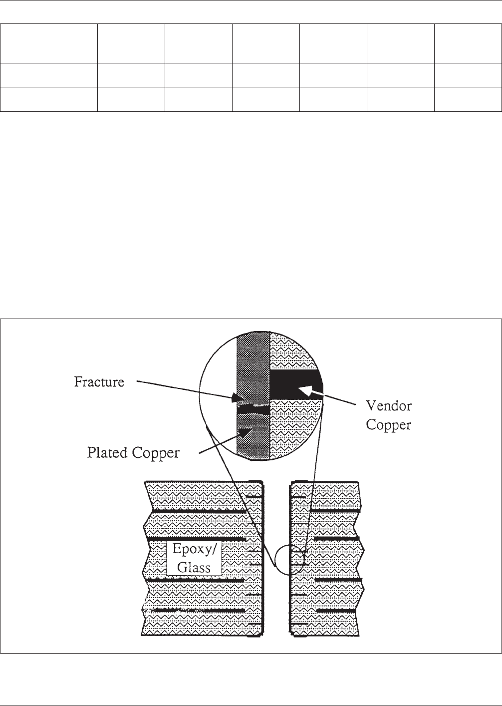
Even good quality PTVs will eventually fail and will typi-
cally do so as the result of a PTV barrel fracture near the
center of the barrel as is illustrated in Fig. B-1.
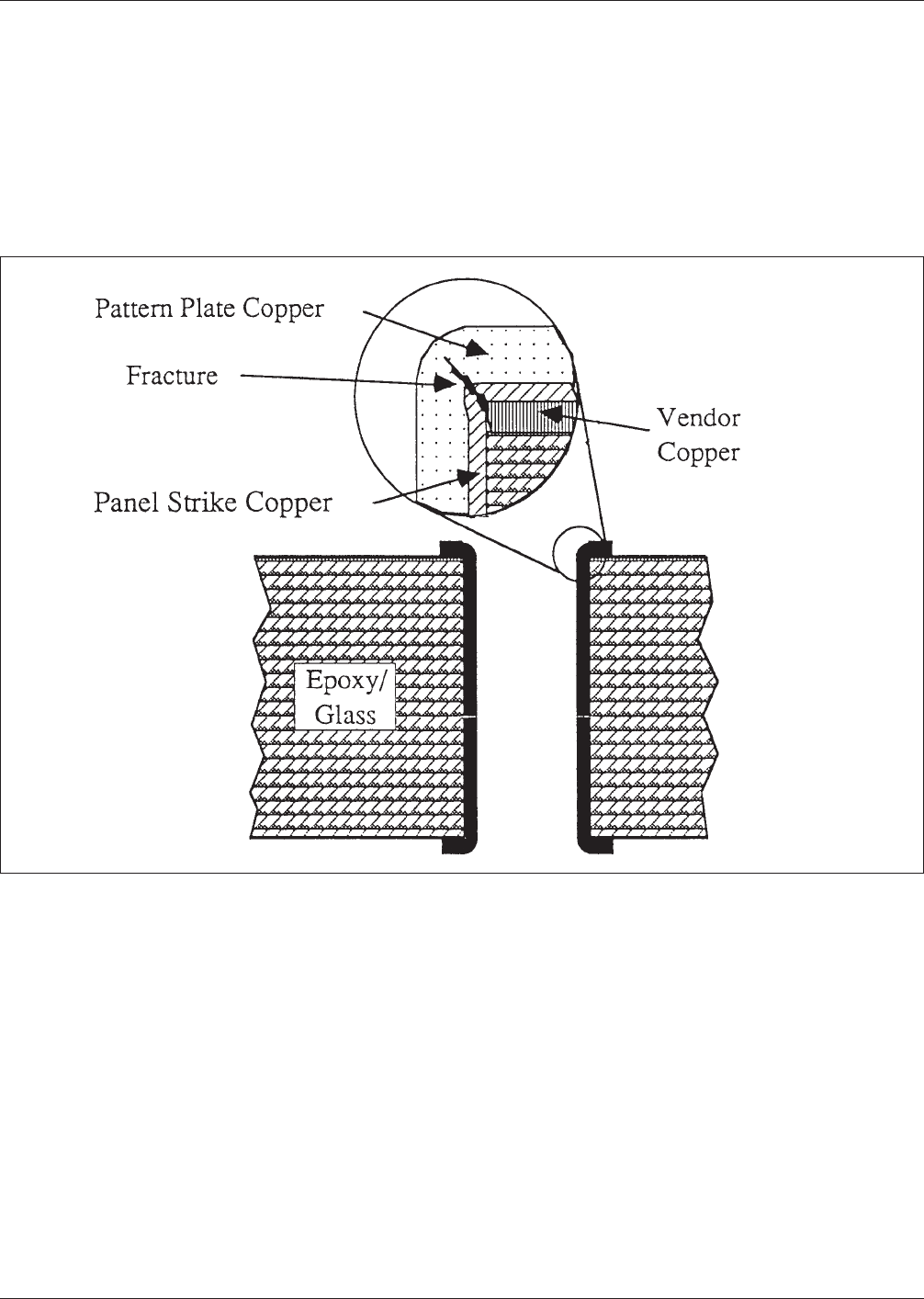
PTV failures can also occur as the result of PTV shoulder
fractures (see Fig. B-2) and internal land fractures. Failures
of these types typically are the consequence of an inad-
equate material choice for the vendor copper foils [Ref.
B-7: 14] used for the laminates or some processing error.
Of the ∆T≈180°C thermal excursion during the soldering
process, ∆T≈100°C is below T
g
at a mismatch in the
Table B-1 Estimates of Tensile Properties of Copper Deposit Inside the PTVs [Reference B-7:10]
Test
∆T
[°C]
Fatigue Life
N
f
[cycles]
Barrel Stress
σ
[MPa/ksi]
Strain Range
∆ε
max
(eff)
[%]
Copper
Strength
S
u
[MPa/ksi]
Minimum
Ductility
D
f
[%]
IEC Hot Oil
Thermal Shock
235 32 219/31.8 4.5 281/40.7 20.6
Temperature
Cycle/Shock
190 150 177/25.7 2.2 281/40.7 23.3
Figure B−1 Cross-Section Schematic of a PTV With a Barrel Fracture Near the Center of the MLB
IPC-D-279 July 1996
52
CTEs of ∆α≈20-69 ppm/°C, whereas ∆T≈80°C is above T
g
at a mismatch in the CTEs of ∆α≈168-331 ppm/°C. This
results, for a 1.60 mm thick MLB, in an expansion mis-
match between ~25 and 50 µm, providing the severe load-
ing conditions that can lead to fractures in the PTV barrels
or shoulders as well as the cracking of inner copper layers
near the MLB surface.
The most typical failure mode, however, is the fracture of
the PTV copper barrel, which is the primary subject here.
In Section B-2.0 on reliability modeling, an attempt is
made to distinguish between three different quality aspects
of PTVs. One of these is related to the quality of the PTV
walls as the result of the drilling and desmear processes,
and two to the plating quality in terms of the plating uni-
formity ‘dog-boning’ and the reduced material properties in
the center of the PTV.
B-1.3.2 Impact of Assembly Processes and ESS Proce-
dures
The most severe stress condition and threat to reli-
ability for PTVs takes place during the solder reflow pro-
cesses necessary to make circuit board assemblies. Because
of the large differences in the CTEs for the copper and the
MLB resin, the larger the temperature excursions the larger
is the resulting thermal expansion mismatch causing
stresses in the PTV copper barrel and shoulders.
The large temperature excursions during the soldering and
solder reflow processes combine with the difference in the
CTE between the glass-reinforced epoxy layers surround-
ing the PTV and the plated copper of the PTV barrel to
create tensile stresses in the copper barrel and bending
stresses at the PTV shoulder due to the PTV land rotating
as a result of the large z-direction (the direction perpen-
dicular to the plane of the MLB) expansion of the epoxy.
The CTE of FR-4 in the z-direction is typically 38-97
ppm/°C below the glass transition temperature, Tg, and
186-349 ppm/°C above T
g
[Refs. B-7: 15-20], whereas
electrodeposited copper foils have a CTE of about 17±2
ppm/°C.
Environmental Stress Screening (ESS) procedures, in order
to be effective, need to resemble solder reflow excursions
in their severity. Therefore, ESS cycles have a similar
impact as do solder reflow excursions.
It is during these excursions to solder reflow temperatures
during solder reflow operations or ESS procedures that
PTV barrel cracks can initiate due to overstressing and
Figure B−2 Schematic Cross-Sectional View of a PTV with a Shoulder Fracture in a printed board
July 1996 IPC-D-279
53

subsequent thermal excursions serve to propagate such
cracks to complete separation and failure.
B-1.3.3 Impact of Test Procedures and Cyclic Operating
Environments
During cyclic temperature testing and
operational use of the product, cyclic thermal excursions
can also lead to fractures and failure due to cyclically accu-
mulating fatigue damage. The severity of the fatigue dam-
age is dependent on the severity of the operational environ-
ment of the application. In Table A-1 guidelines as to the
possible use environments for nine of the more common
electronic applications are illustrated. The fatigue damage
caused first by the thermal excursions during processing
and assembly, then by cyclic temperature testing, and
finally during product use is cumulative and needs to be
accounted for in a reliability analysis.
B-2.0 RELIABILITY PREDICTION MODELING
The fatigue behavior of metals can be described by [Refs.
B-7: 21, 22]
N
f
−0.6
D
f
0.75
+0.9
S
u
E
[
exp(D
f
)
0.36
]
0.1785log
10
5
N
f
−∆ε = 0
(Eq. B-1)
where
N
f
= mean fatigue life, cycles-to-failure,
D
f
= fracture ductility, plastic strain at fracture, of the PTV
copper deposit,
S
u
= tensile strength of the PTV copper deposit,
E = modulus of elasticity of the PTV copper deposit,
∆ε = total cyclic strain range.
The relationships underlying Equation B-1 were developed
to be able to predict the fatigue life from tensile properties
and brought about a unified ductility-dependent low-cycle
fatigue and strength-dependent high-cycle fatigue [Ref.
B-7: 23] approach. Equation B-1 has been used for some
major study programs [Refs. B-7: 2, 11, 24] and the devel-
opment of test methods [Refs. B-7: 12, 13].
The full determination of the stresses and strains in the
PTV barrel requires a complex and expensive FEA [Refs.
B-7: 7-10] which goes significantly beyond the needs for a
reliability estimate. For the purposes of DfR and a reliabil-
ity estimate, the stresses and strains can be estimated with
adequate accuracy using a practical engineering approach
[Ref. B-7: 10]. The closed form approach, given below,
assumes no land rotation—a conservative assumption—and
calculates the average stresses and strains assuming a uni-
form stress and strain distribution. This last assumption is
non-conservative; corrections (see Eqs. B-11 through
B-14), based on empirical test results, need to be applied.
Depending on the magnitude of the PTV barrel deforma-
tion, the average stresses are calculated by
σ
avg
=
(α
E
−α
Cu
)∆TA
E
E
E
E
Cu
A
E
E
E
+A
Cu
E
Cu
, for σ
avg
≤ S
y
(Eq. B-2)
or
σ
avg
=
[
(α
E
−α
Cu
)∆T+S
y
E
Cu
−E
Cu
≠
E
Cu
E
CU
≠
]
A
E
E
E
E
Cu
≠
A
E
E
E
+A
Cu
E
Cu
≠
, for σ
avg
>S
y
(Eq. B-3)
where
A
E
=
π
4
[d
E
2
−d
2
]
(Eq. B-4)
and
A
Cu
=
π
4
[d
2
−(d−2t)
2
]
(Eq. B-5)
and where
σ
avg
= PTV barrel stress;
S
y
= PTV barrel copper yield strength, typically ~172
MPa;
α
E
= CTE of MLB in thickness direction, for excursions
above T
g
the larger CTE at those temperatures
needs to be considered, typically ~65 ppm/°C @
<T
g,
315 ppm/°C @ >T
g
;
α
Cu
= CTE of copper, typically ~18 ppm/°C;
∆T = temperature range of thermal cycling;
A
E
= area of loading influence of MLB;
A
Cu
= area of PTV barrel;
E
E
= modulus of elasticity of epoxy, typically ~3.5 GPa;
E
Cu
= modulus of elasticity of PTV copper, typically ~83
GPa for acid- plated copper and 35 ~GPa for
pyrophosphate-plated copper;
E
Cu
≠ = modulus of elasticity of PTV copper, typically
~0.7 GPa;
h = thickness of MLB;
d = drilled PTV diameter;
d
E
= diameter of MLB dielectric surrounding the PTV
and influencing the PTV loading;
t = thickness of copper deposit in PTV barrel.
The average strains in the PTV barrel are determined from
∆ε
avg
=
(α
E
−α
Cu
)∆TA
E
E
E
A
E
E
E
+A
Cu
E
Cu
, for σ
avg
≤ S
y
(Eq. B-6)
and
∆ε
avg
=
(α
E
−α
Cu
)∆TA
E
E
E
−S
y
A
Cu
E
Cu
−E
Cu
≠
E
Cu
A
E
E
E
+A
Cu
E
Cu
≠
, for σ
avg
> S
(Eq. B-7)
where
∆ε
avg
= the cyclic strain range during thermal cycling.
The diameter of MLB dielectric material surrounding a
PTV and influencing the PTV loading, d
E,
is a measure of
IPC-D-279 July 1996
54