N7201A654E.pdf - 第10页
NPM- TT2 EJM1EE-BP-04N-01 T erms used in the button on the screen may differ from the ones in explanation. Remarks ● Homing axis S-10 1 2 1 + 2 A A How to read operating instructions… 2 V isual procedure/operation by rea…
NPM-TT2 EJM1EE-BP-04N-01
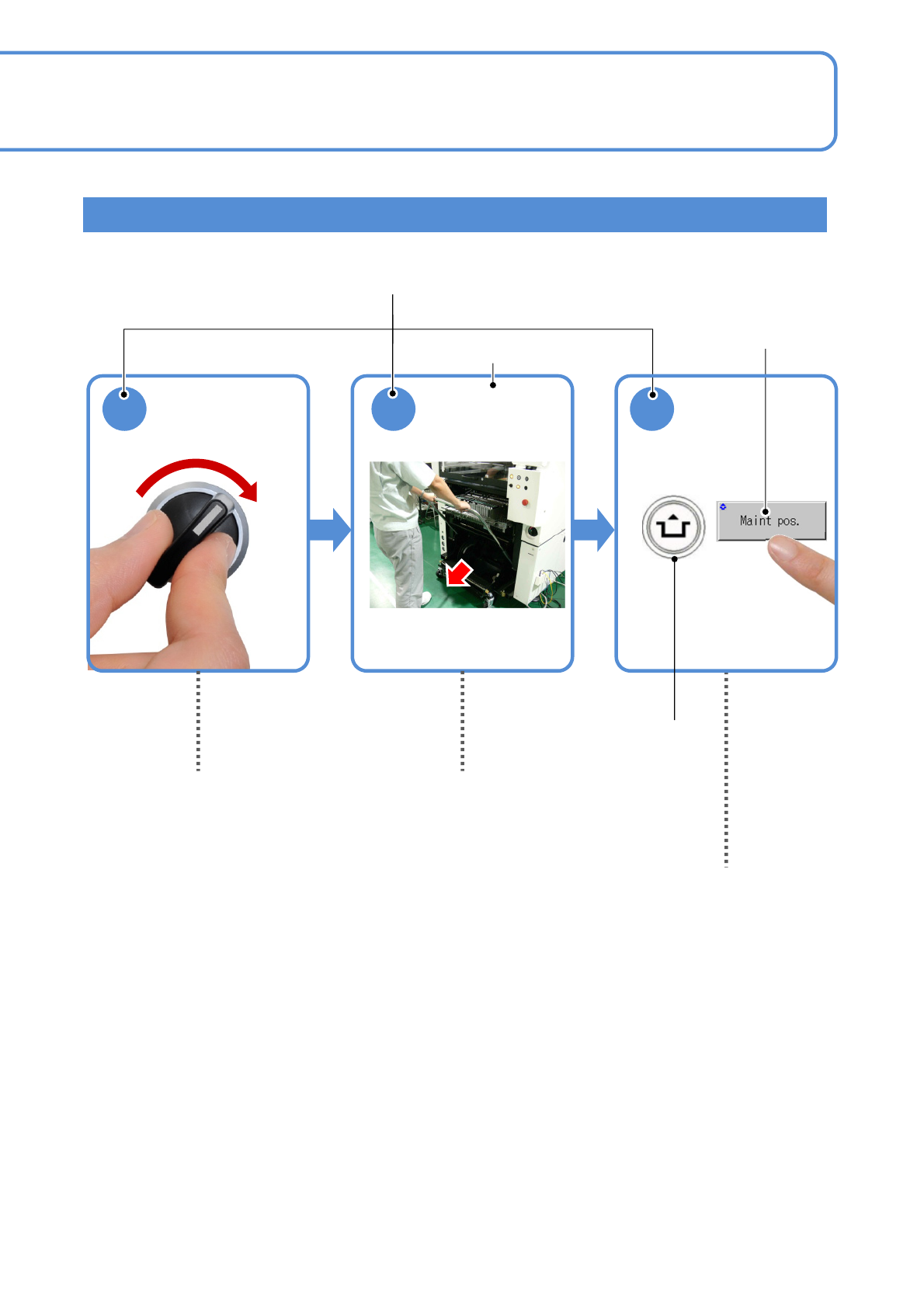
SERVO
ON
1 2 3
Detach the
feeder cart.
(→P.3-2)
Shows to turn in the
direction of the arrow.
Operation switch
Contents of operation
Operating procedure
Operation button
S-9
Shows to push another switch or button
while holding down the ACTIVATION
switch.
(Position of switches may vary)
Indicates to draw out to
the arrow direction.
Visual procedure/operation by reading
NPM-TT2 EJM1EE-BP-04N-01
Terms used in the button on the screen may differ from
the ones in explanation.
Remarks
● Homing axis
S-10
1
2
1
+
2
A
A
How to read operating instructions… 2
Visual procedure/operation by reading
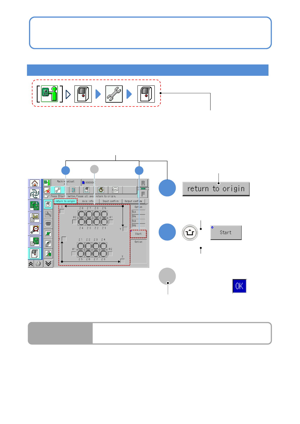
Operation procedure
Operation mode button, press the button
that shows each level of operation.
Shows to push the
operation button.
Shows to push another button
while holding down the
ACTIVATION switch.
Shows the operation results.
(Completes continuous preparation.)
Run Results
Screen explanation

NPM-TT2 EJM1EE-CT-01T-01
Table of Contents
2
-1
Error message
-1-1
How to read error messages
-1-2
Self-diagnosis errors
-1-3
Single stop errors
-1-4
Emergency stop errors
-2
Warning message
Solutions
to errors
1
What if
-1
What if
-1-1
Pickup motion error
-1-2
Placement error
-1-3
Transfer error
S-11
4
3
-1
Recognition information
-1-1
Recognition information after production
(memory function)
-2
Recognition error message
-2-1
Recognition error message lists
-1
Load arrangement drawings
-2
Load list
-2-1
Motor list
-2-2
Solenoid list
-2-3
Sensor list
-2-4
Switch list
-2-5
Regulator list
Solutions to
recognition
Load
arrangement
drawings