00197973-10_SM_MaterialTower.pdf - 第152页
Gripper 0019797 3 - 10 / 02 , 2016 7- 34 © ASM SIPLACE Mat. Tower St ora ge Ser vice Manu al Step 3 Switch the storage dev i ce on an d press the emergency stop b utton to prevent a ny movement. The sensor alignment must…
00197973-10 / 02 , 2016 Gripper
SIPLACE Mat. Tower Storage Service Manual © ASM 7-33
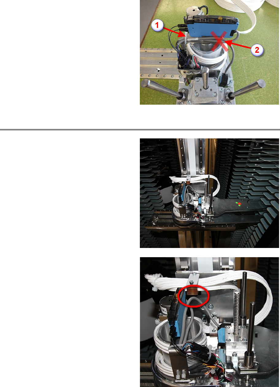
Reconnect the sensor cable and apply the cable
tie (1). Do not apply a cable tie at the position
indicated on the picture (2). Take care that the
direction of the cable is si
milar as shown in the
picture. Make sure the cable is completely free
between the sensor and the cable tie (1).
Step 2
The cable should be i
n a certain position over
the whole move range of the gripper. To test the
correct alignment, move the gripper into the
position shown on the picture.
The sensor cable should not touch the Leoni
cable holder at any move of the gripper.
Gripper 00197973-10 / 02 , 2016
7-34 © ASM SIPLACE Mat. Tower Storage Service Manual
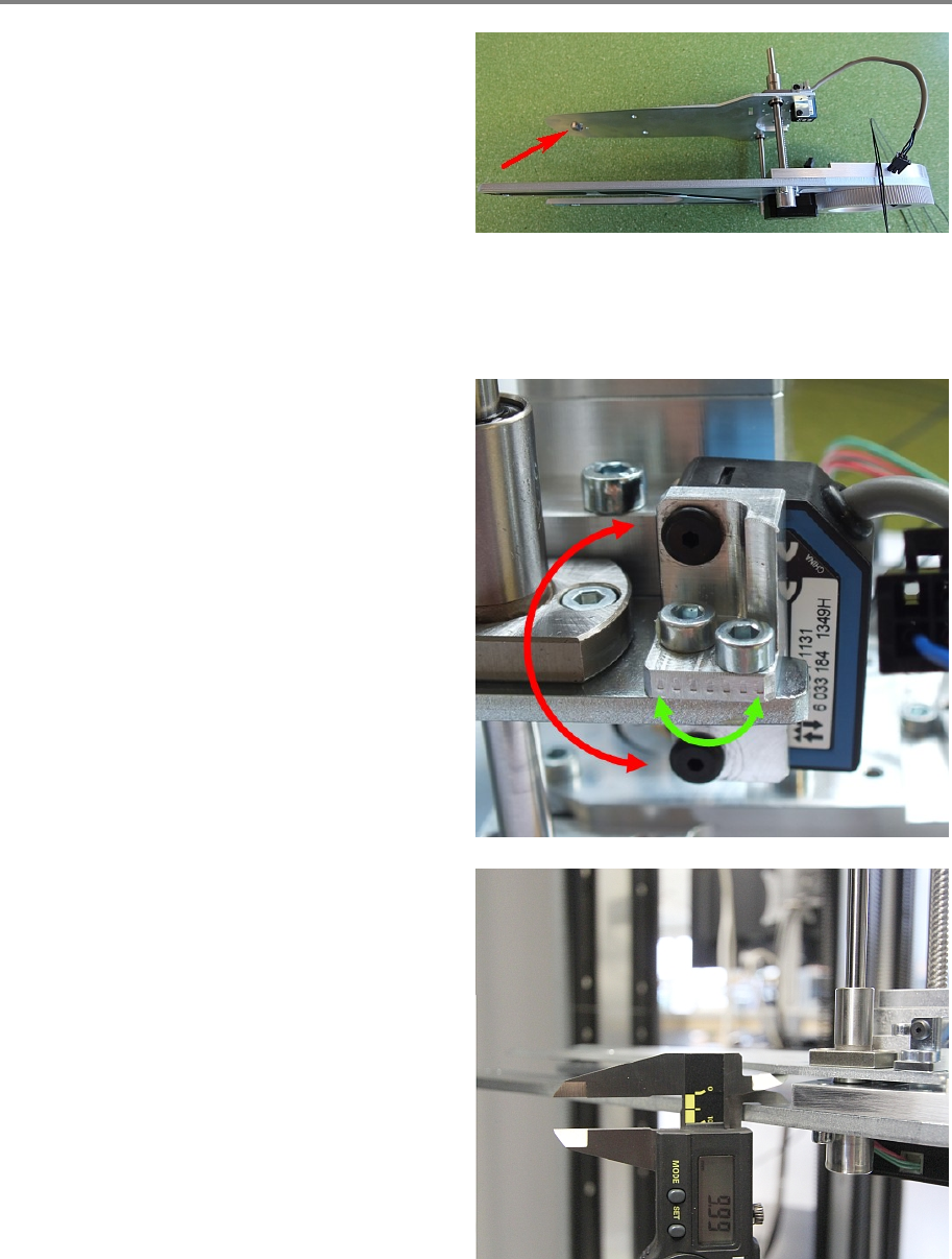
Step 3
Switch the storage device on and press the
emergency stop button to prevent any
movement.
The sensor alignment must be properly adjusted
considering two points:
• The sensor's red light must be precisely
adjusted to the nipple at the front of the
gripper. Shown in picture.
• At the initialization point the gripper
clearance must be 10 mm ± 0.3 mm.
The two black screws are for the vertical
adjus
tment and the two metallic screws for the
horizontal adjustment as shown in the picture. If
the whole sensor has been exchanged then only
the black screws have been loosened, meaning
the adjustment is easier.
To get the correct position for initialization move
the gripper manually to a position where the
clearance is
10 mmand then setup the sensor
that the green AND red LED are on.
00197973-10 / 02 , 2016 Gripper
SIPLACE Mat. Tower Storage Service Manual © ASM 7-35
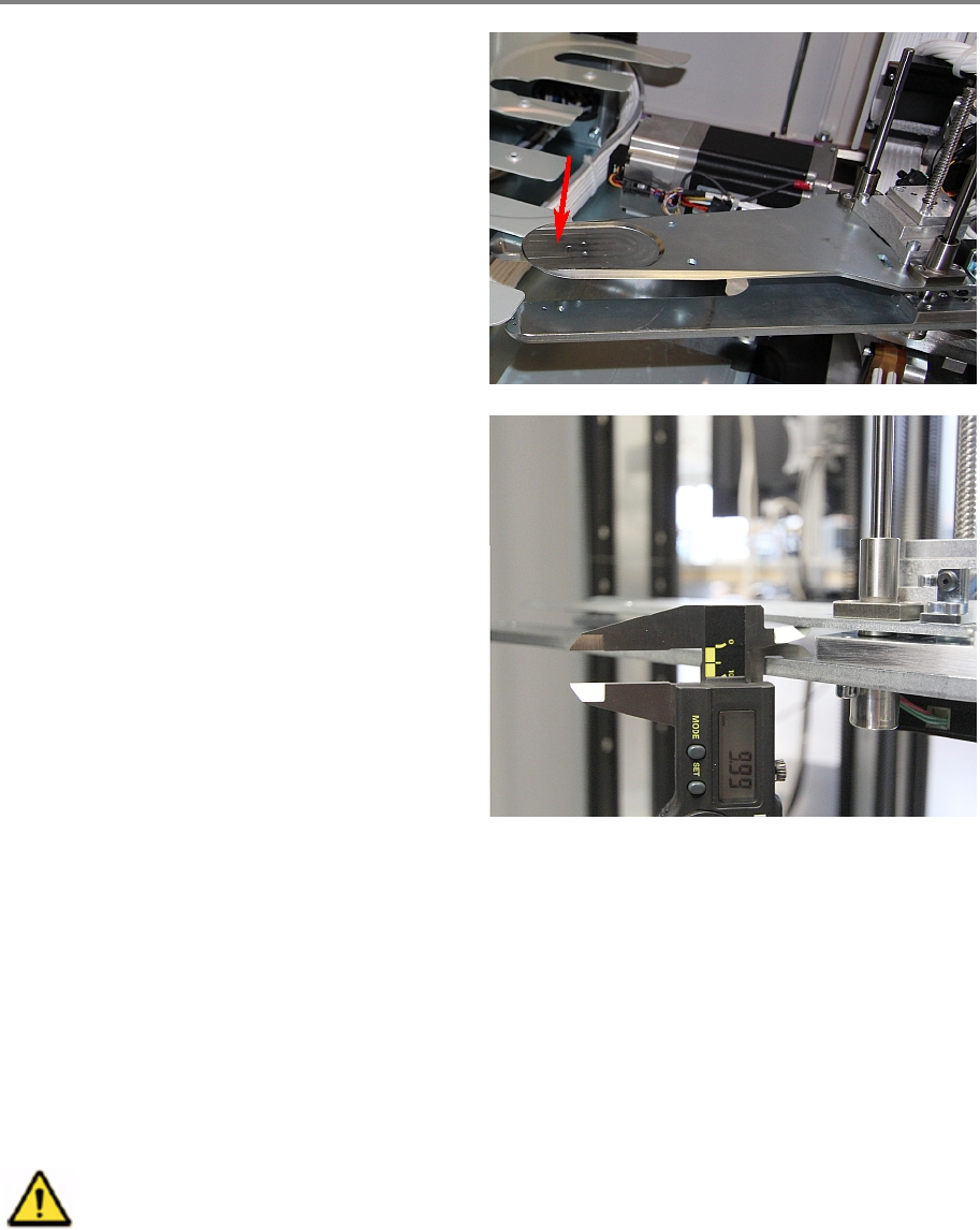
Step 4
By hand open the gripper for around 4cm. Shake
the tip of the gripper an check that the green
LED on the sensor is always on and the red LED
is never flickering.
Close the doors, release the emergency stop and
start up the eStorage software.
Log in and initialize.
Open the door and measure again the clearance
after initialization. It should be
10 mm ± 0.3
mm
. If not, repeat step 3 and 4.
7.6 Reflection sensor WT2F-P140
7.6.1 Introduction
This modification instruction describes how to exchange the reflection sensor WT2F-P140 on
SIPLACE Material Tower.
Spare part number: 03124521-01
Before starting the maintenance, read the Safety instructions carefully.
7.6.2 Tools, Material and Scheduling
For an effective and efficient maintenance, the following resources have to be provided: