00197973-10_SM_MaterialTower.pdf - 第258页
Serv ice D oor Monit oring 0019797 3 - 10 / 02 , 2016 12 - 12 © ASM SIPLACE Mat. Tower St ora ge Serv ice Manu al Move the comp onent labeling accordingly and attach the provi ded labels.
00197973-10 / 02 , 2016 Service Door Monitoring
SIPLACE Mat. Tower Storage Service Manual © ASM 12-11
Preparation of electrical cabinet
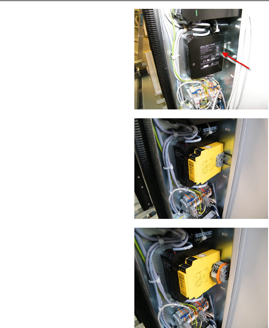
Move the 24 V power supply (T1), completely to
the left.
Mount the safety relay (SR1) to the profile rail,
close to the 24 V supply. Mount a distance
holder right to the safety relay.
Mount the cable terminal (X800) to the profile
rail, together with a distance holder.
Service Door Monitoring 00197973-10 / 02 , 2016
12-12 © ASM SIPLACE Mat. Tower Storage Service Manual
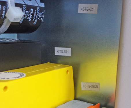
Move the component labeling accordingly and
attach the provided labels.
00197973-10 / 02 , 2016 Service Door Monitoring
SIPLACE Mat. Tower Storage Service Manual © ASM 12-13
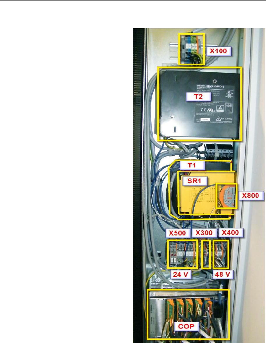
Cabling of the Safety Door Functionality
For a proper cabling, it is important to define the units. To keep it simple, the units have the same
and official names and numbers of the schematics.
(X100) Power Input Terminal
(T2) Power Supply 48 V
(T1) Power Supply 24 V
(SR1) Safety Relay
(X800
) Power Auxiliary Terminal
(X500) 24 V Terminal
(X300) Terminal
(X400) 48 V Terminal
(COP) Indel Electronic
(DoorL) Door Sensor Cable Left
(DoorR) Door Sensor Cable Right