00197973-10_SM_MaterialTower.pdf - 第256页
Serv ice D oor Monit oring 0019797 3 - 10 / 02 , 2016 12 - 10 © ASM SIPLACE Mat. Tower St ora ge Serv ice Manu al Rout the cable all along the 230 V cable and fix it by usin g cable ties togethe r with the 230 V cabl e o…
00197973-10 / 02 , 2016 Service Door Monitoring
SIPLACE Mat. Tower Storage Service Manual © ASM 12-9
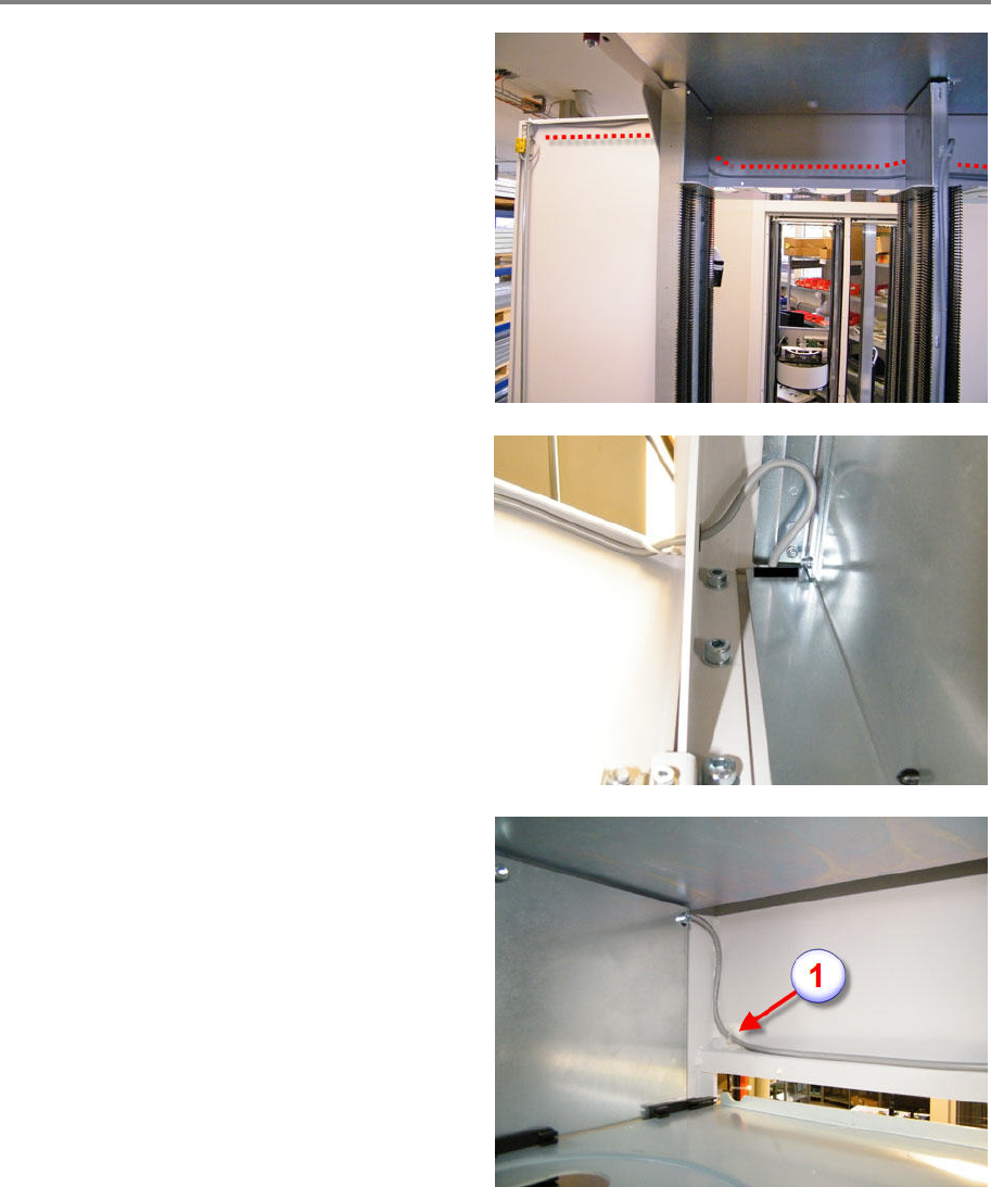
Routing of the Sensor Cable
Starting on the right sid
e of the machine, see the
overview picture to get an idea of the routing of
the sensor cable.
Route the cable through the cable bushing
and
through the slot of the chassis (see picture).
Make sure the cable has a loop after the bushing
for the length compensation (opening and
closing the door).
If cabling a SIPLACE Material Tower Regular, skip
this step.
If cabling a SIPLACE Material Tower Large,
mount an adhesive pad on the left side on the
most left rack (1).
Fix the cable by means of a cable tie.
Service Door Monitoring 00197973-10 / 02 , 2016
12-10 © ASM SIPLACE Mat. Tower Storage Service Manual
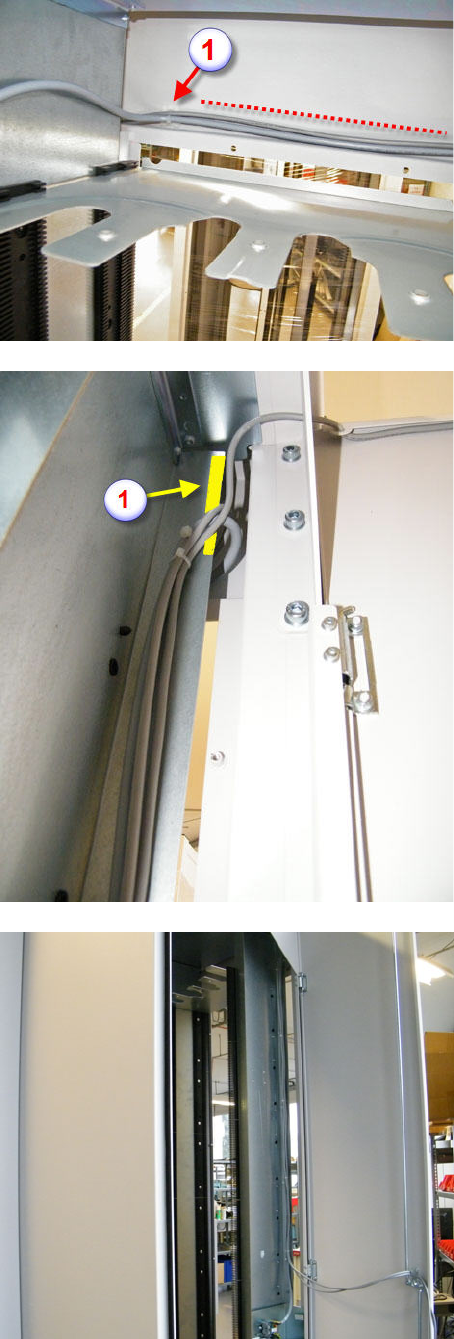
Rout the cable all along the 230 V cable and fix it
by using cable ties together with the 230 V cable
on the existing pads (1).
Going to the left side of the machine, route the
cable of the left door sensor through the
bushing. Make sure the cable has a loop after the
bushing for the length compensation (opening
and closing the door).
Route both sensor cables along the 230 V cable
and use the existing pads to fix the cables. Pay
attention to a proper cabling for better
recognition of right and left sensor cable
afterwards or mark the cables at the end.
Check the position of the edge protector (1), so
that the cables are protected
properly.
During preparation of the electrical cabinet, the
sensor cables can be put away as shown on
picture.
00197973-10 / 02 , 2016 Service Door Monitoring
SIPLACE Mat. Tower Storage Service Manual © ASM 12-11
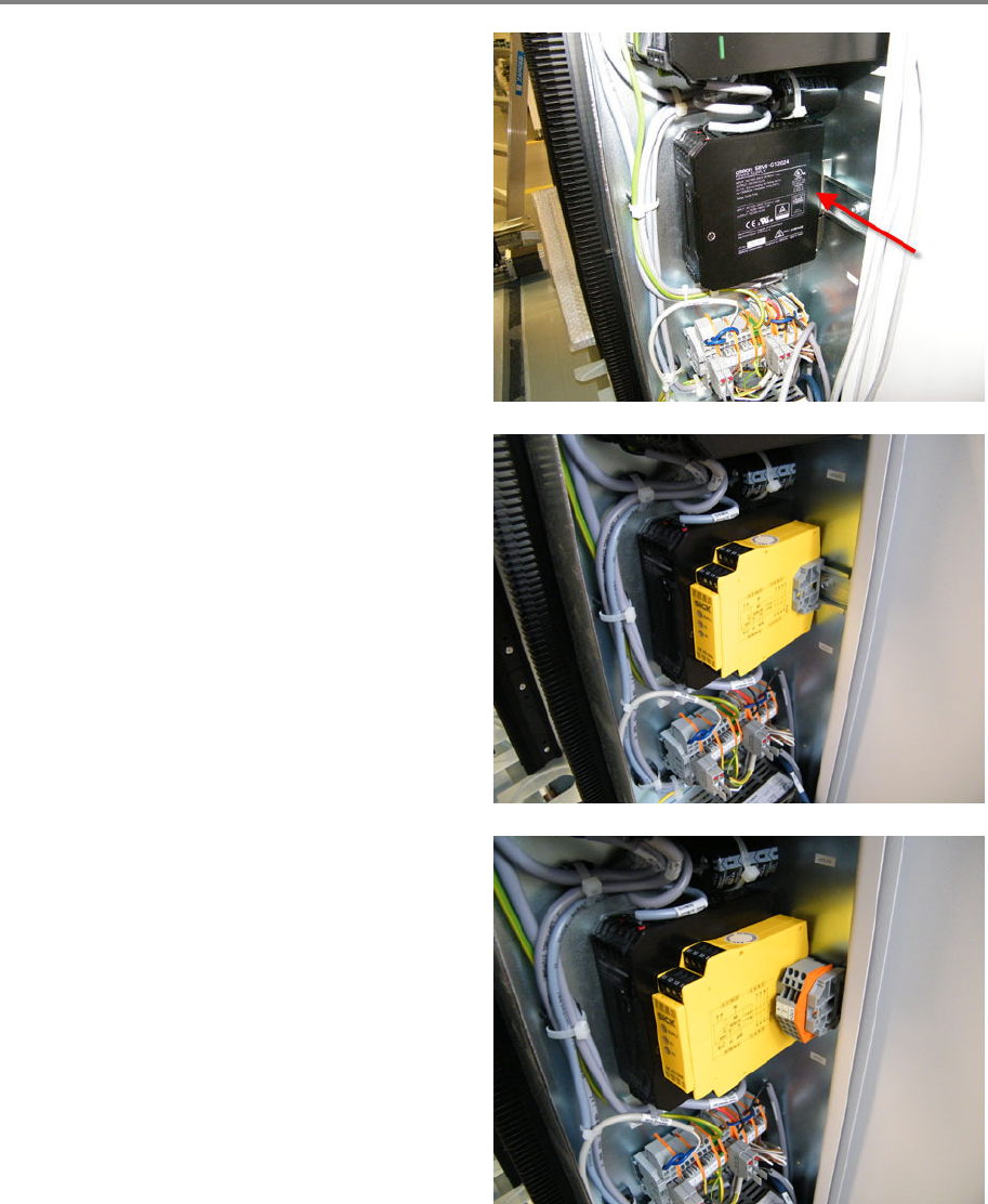
Preparation of electrical cabinet
Move the 24 V power supply (T1), completely to
the left.
Mount the safety relay (SR1) to the profile rail,
close to the 24 V supply. Mount a distance
holder right to the safety relay.
Mount the cable terminal (X800) to the profile
rail, together with a distance holder.