00197973-10_SM_MaterialTower.pdf - 第176页
Portal 00197 973 - 10 / 02 , 2016 8- 12 © ASM SIPLACE Mat. Tower St ora ge Ser vice Manu al 8.4 Reel Detecto r 8.4.1 Introducti on This modification instructi on describes how t o change the reel detection sens or on SIP…
00197973-10 / 02 , 2016 Portal
SIPLACE Mat. Tower Storage Service Manual © ASM 8-11
Step 3
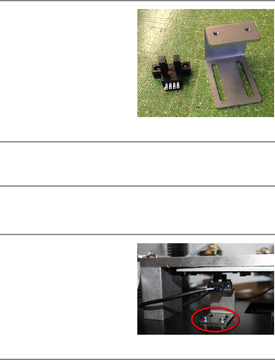
Exchange the old sensor with a new one.
Step 4
Mount the sensor holder on its place and plug the electrical connectors as described in step 2 and
1.
Step 5
Plug in the power connector and switch on the machine.
Assure that noone is manipulating the software whilst you are inside the machine.
Step 6
Setup the position of the sensor that following
conditions are fulfilled:
Fully open the portal door. The red LED must be
on, meaning the sensor is activated.
Fully close the portal door. The red LED must be
of, meaning the senso
r is deactivated.
Step 7
Remove all tools and close the doors of the machine.
Connect the compressed air supply.
Initialize the machine by means of the software.
Portal 00197973-10 / 02 , 2016
8-12 © ASM SIPLACE Mat. Tower Storage Service Manual
8.4 Reel Detector
8.4.1 Introduction
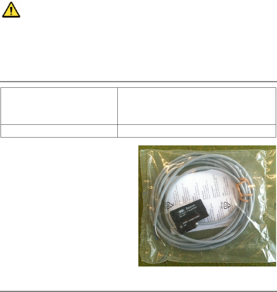
This modification instruction describes how to change the reel detection sensor on SIPLACE
Material Tower.
Spare part number: 03126680-01
Before starting the maintenance, read the Safety instructions carefully.
8.4.2 Tools, Material and Scheduling
For an effective and efficient maintenance, the following resources have to be provided:
Required Tools / Auxiliary Material / Spare parts
Tools: Allen key Nr. 3 and 4
Slotted screw driver nr. 1
Side cutter
Auxiliary Material: Cable ties
Spare parts:
03126680
-01, reel detection sensor
Time needed
Schedule around 30 minutes for this task.

00197973-10 / 02 , 2016 Portal
SIPLACE Mat. Tower Storage Service Manual © ASM 8-13
8.4.3 Prerequisites
For a safe and efficient maintenance, the following prerequisites have to be fulfilled:
Personnel:
• Any work with or at the equipment must be carried out by skilled and
trained personnel in accordance with the locally applicable
regulations.
• Inform all involved persons regarding the currently running
maintenance works.
Machine loading:
• NO item must be unloaded.
Machine operating
condition:
• Shut down
Main electrical
power:
• Equipment disconnected from power supply system. The Main Switch
(switched off) locked by means of a padlock to secure the main switch
against unintentional switching on.
Compressed air /
Nitrogen (if used):
• Equipment disconnected from compressed air or nitrogen supply.
Access:
•
Open the maintenance door on the left side.