00197973-10_SM_MaterialTower.pdf - 第203页
0019797 3 - 10 / 02 , 2016 Electronics SIPLACE Mat. Towe r St ora ge Serv ice Manual © ASM 9-5 9.2 24V Supp ly 9.2.1 Introducti on This mod ification i nstruction describes how to ch ange the 24V power suppl y on SIPLACE…
Electronics 00197973-10 / 02 , 2016
9-4 © ASM SIPLACE Mat. Tower Storage Service Manual
Step 3
Reinsert the new Indel controller. And fix the
screws.
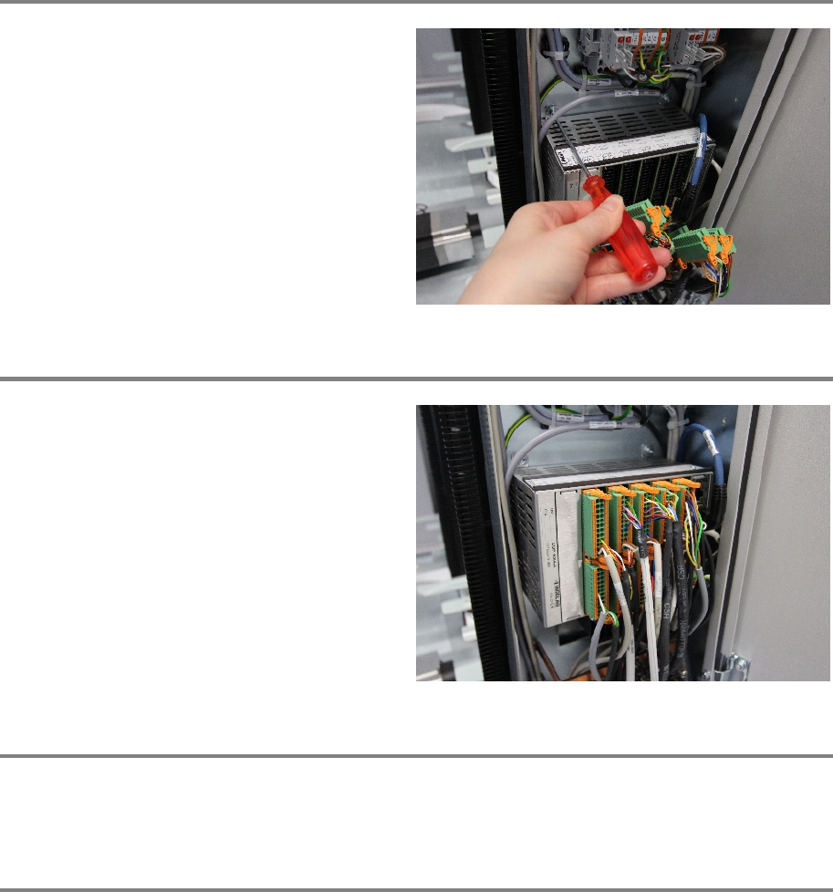
Step 4
Fasten all cable connection in their correct slots.
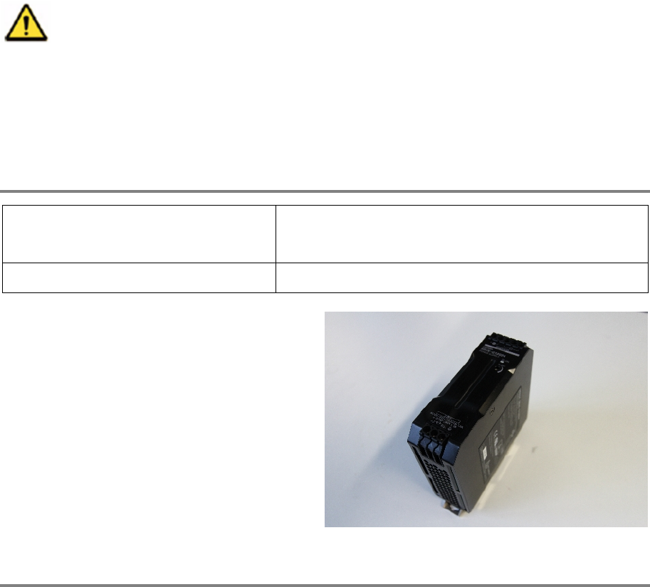
Step 5
Remove all tools, close the door of the machine, plug in the power connector and switch on the
machine.
Step 6
In the software, in System - Storage Devices/Units select the appropriate machine in the table
and press Load.
In tab Axes calibration calibrate the Y axis and follow the instructions given by the software.
00197973-10 / 02 , 2016 Electronics
SIPLACE Mat. Tower Storage Service Manual © ASM 9-5
9.2 24V Supply
9.2.1 Introduction
This modification instruction describes how to change the 24V power supply on SIPLACE Material
Tower.
Spare part number: 03124517-01
Before starting the maintenance, read the Safety instructions carefully.
9.2.2 Tools, Material and Scheduling
For an effective and efficient maintenance, the following resources have to be provided:
Required Tools / Auxiliary Material / Spare parts
Tools: Slotted screw driver nr. 2
Voltmeter
Auxiliary Material: none
Spare parts:
03124517
-01, 24V power supply
Time needed
Schedule around 10 minutes for this task.
9.2.3 Prerequisites
For a safe and efficient maintenance, the following prerequisites have to be fulfilled:
Electronics 00197973-10 / 02 , 2016
9-6 © ASM SIPLACE Mat. Tower Storage Service Manual
Personnel:
• Any work with or at the equipment must be carried out by skilled and
trained personnel in accordance with the locally applicable
regulations.
• Inform all involved persons regarding the currently running
maintenance works.
Machine loading:
• Stored items do not have to be unloaded.
Machine operating
condition:
• Shut down
Main electrical power:
• Equipment disconnected from power supply system. Fully
disconnect the mains power cable and secure against
unintentional plugging.
Compressed air /
Nitrogen (if used):
• Equipment disconnected from nitrogen.
Access:
• Open the door on the left side of the machine.
• The electrical units are located in the bottom right corner.
9.2.4 Exchange steps
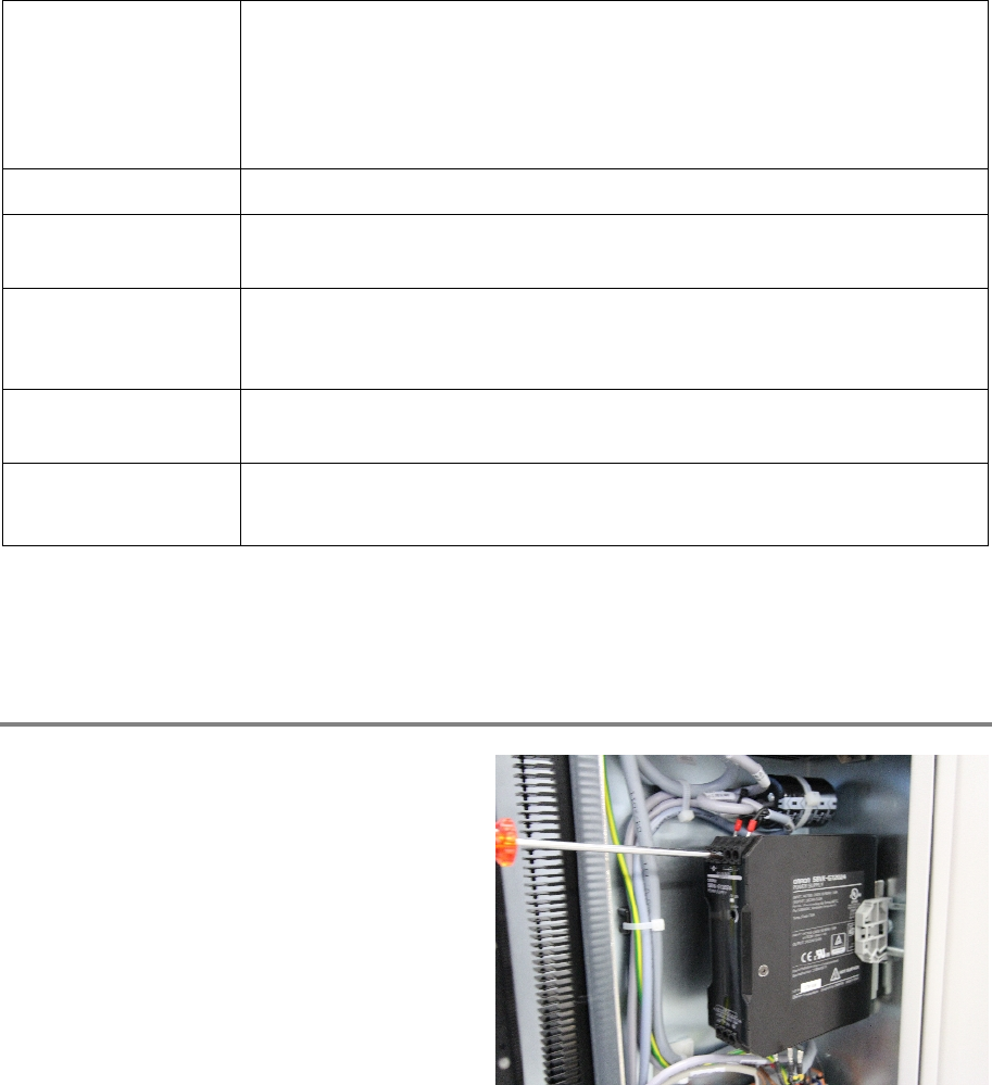
Step 1
Unscrew all cable connections on the top and
the bottom of the power supply.
Make sure to label the cables or mark their
proper slot in the power supply.