00196504-02_UM_X-Serie_SR70X_EN.pdf - 第129页
User manual SIPLACE X-series Technical data for the machine From software version SR.70x.x x 01/2011 EN edition Placement head 129 3 Fig. 3.5 - 5 SIPLACE MultiSt ar - back view , function groups part 3 (1) Comp onent sen…
Technical data for the machine User manual SIPLACE X-series
Placement head From software version SR.70x.xx 01/2011 EN edition
128
3
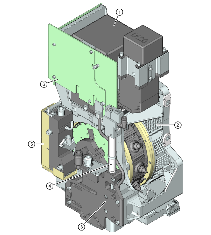
Fig. 3.5 - 4 SIPLACE MultiStar - front view, function groups part 2
(1) C&P component camera, type 30, 27 x 27, digital
(2) Torque motor for the star drive
(3) Z drive (linear motor)
(4) Return cylinder
(5) Pressure control valve
User manual SIPLACE X-series Technical data for the machine
From software version SR.70x.xx 01/2011 EN edition Placement head
129
3
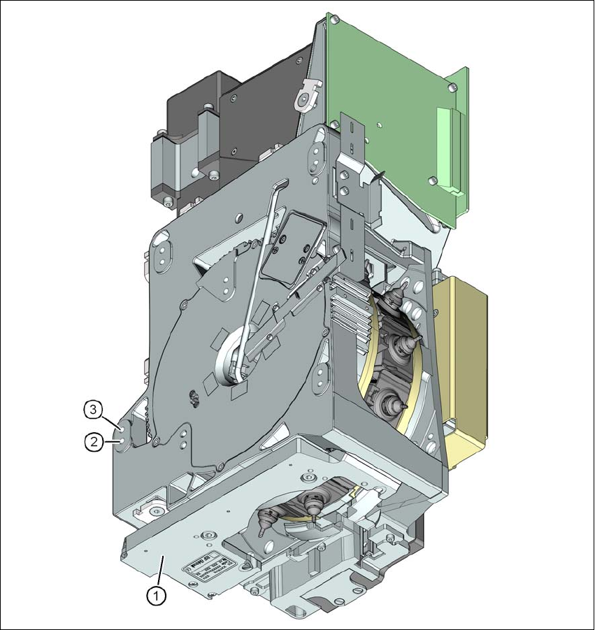
Fig. 3.5 - 5 SIPLACE MultiStar - back view, function groups part 3
(1) Component sensor
(2) Mounting position for component heights up to 11.5 mm
(3) Mounting position for component heights up to 6 mm
3.5.2.1 Description
The MultiStar brings together the two opposing properties of high placement rate and high flexi-
bility. For small components up to 27 x 27 mm², the MultiStar uses the Collect&Place method, i.e.
works with a high placement rate. The components are optically centered with the integrated com-
Technical data for the machine User manual SIPLACE X-series
Placement head From software version SR.70x.xx 01/2011 EN edition
130
ponent camera. With large component up to 50 x 40 mm², the placement head works on the
Pick&Place principle in which the components are optically centered with the stationary camera.
It was this combination of the two placement procedures (C&P and P&P) that gave the MultiStar
its name. It is abbreviated to CPP head.
The 12 segments of the CPP head are arranged in a star. A high-torque motor turns the star about
the horizontal axis, known as the star axis.
Each segment has a separate DP drive for rotating the nozzle. The nozzles are therefore no lon-
ger rotated into the correct position at a single head station. They can be rotated into their place-
ment position at any time and independently of one another.
Each segment has a separate vacuum generator. This greatly reduces the time taken to switch
between vacuum and forced air. It also allows a vacuum check to be carried out in the holding
circuit for each individual nozzle.
The Z drive for the segments is implemented with a linear motor with linear path measuring sys-
tem, and is thus extremely precise. In the pick-up/placement position, the Z drive moves the seg-
ments up or down in the vertical direction.
As with all SIPLACE Collect&Place heads, the digital component camera is integrated into the
placement head. This omission of additional traversing paths for the optical centering of the com-
ponents contributes to the fast processing speed.
The component sensor on the underside of the placement head measures the components at
the pick-up/placement position. Measurements can be taken at the tip of the nozzle for each
movement of the Z axis, which will give an indication of whether there is a component sticking at
the nozzle and how high the component is.
3.5.2.2 Mounting positions for the SIPLACE MultiStar
The CPP head can be fitted in two different positions on the head mount.
– MultiStar in the upper mounting position
In this position, all components up to 50 x 40 mm² and up to 11.5 mm can be processed. 3
– MultiStar in the lower mounting position
In this position, the CPP head can place components up to 27 x 27 mm² and up to 6 mm high
using the Collect&Place method. 3
Please note the following rules when determining the mounting position:
→ The head height must be the same for all placement heads within a placement area.
→ Always install the CPP head in the upper mounting position if it is combined with the following
modules:
– Stationary component camera
– Matrix tray changer