00196504-02_UM_X-Serie_SR70X_EN.pdf - 第183页
User manual SIPLACE X-series Technical data for the machine From software version SR.70x.xx 01/2011 EN edition X feeder modules 183 3.9.2.10 88 mm X tape feede r module 3 Fig. 3.9 - 12 88 mm X tape feeder module 3 3 88 m…
Technical data for the machine User manual SIPLACE X-series
X feeder modules From software version SR.70x.xx 01/2011 EN edition
182
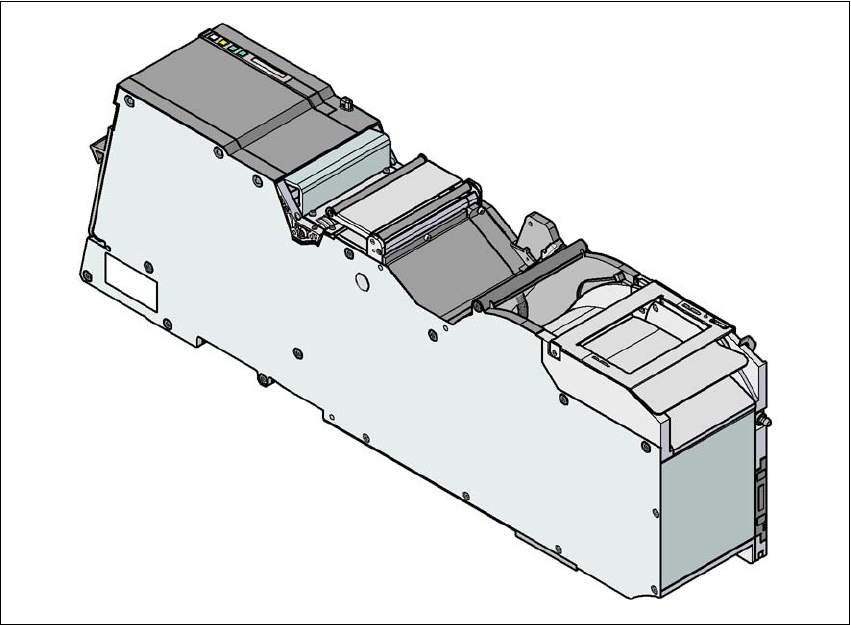
3.9.2.9 72 mm X tape feeder module
3
Fig. 3.9 - 11 72 mm X tape feeder module
3
3
3
72 mm X tape feeder module item no. 00141277-xx
72 mm X tape feeder module with splice sensor item no. 00141297-xx
Width 81.6
Feeder module locations filled 7
Conveyor increment from 4 mm to 80 mm in 4 mm increments
Changeover time for the component tape < 45 s
Changeover time for the preset feeder module
on the machine
≤ 8 s
User manual SIPLACE X-series Technical data for the machine
From software version SR.70x.xx 01/2011 EN edition X feeder modules
183
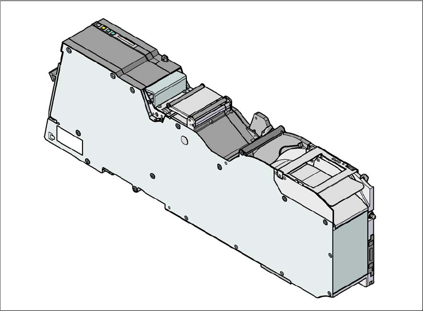
3.9.2.10 88 mm X tape feeder module
3
Fig. 3.9 - 12 88 mm X tape feeder module
3
3
88 mm X tape feeder module item no. 00141278-xx
88 mm X tape feeder module with splice sensor item no. 00141298-xx
Width 105.2 mm
Feeder module locations filled 9
Conveyor increment from 4 mm to 96 mm in 4 mm increments
Changeover time for the component tape < 45 s
Changeover time for the preset feeder module
on the machine
≤ 8 s
Technical data for the machine User manual SIPLACE X-series
X feeder modules From software version SR.70x.xx 01/2011 EN edition
184
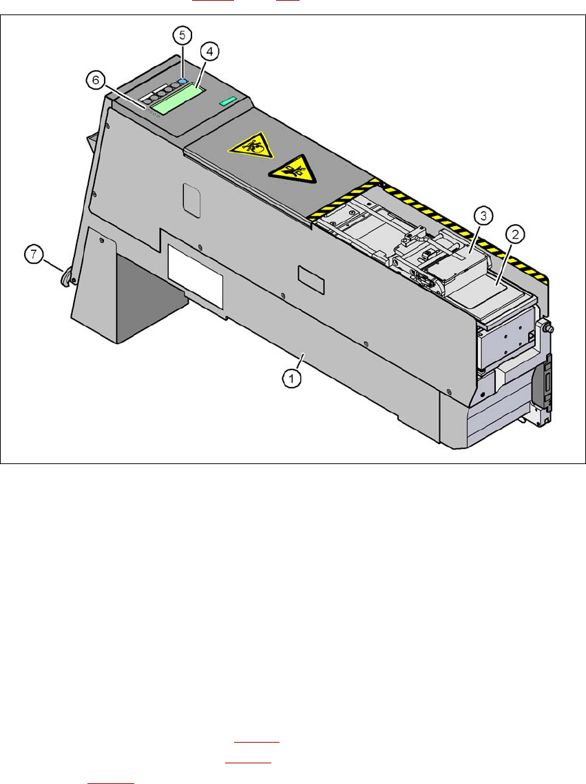
3.9.3 X linear dipping unit (LDU X)
Item no. 00117011-xx Linear dip module for flux / LDU-X
Item no. dip plates see Section 3.9.3.5
, page 186
3
Fig. 3.9 - 13 Linear Dipping Unit (LDU X)
(1) LDU X
(2) Dip plate
(3) Flux container
(4) Display panel (4 lines each with 20 characters)
(5) Operator panel with 6 membrane keys
(6) LED for status displays
(7) EMERGENCY OFF button
3.9.3.1 Description
The X linear dipping unit (item 1 in Fig. 3.9 - 13) is used to wet flip-chip and CSP components with
flux. The flux container item 3 in Fig. 3.9 - 13
) slides with a linear movement over the dip plate
(item 2 in Fig. 3.9 - 13
) and applies the flux at a defined layer thickness in the depression in the
dip plate. The parameters for wetting a component with flux are prescribed in SIPLACE Pro. The