00196504-02_UM_X-Serie_SR70X_EN.pdf - 第66页
Operational safety User manual SIPLACE X-se ries Safety instructions for operating the mach ine F rom software version SR.70x.xx 01/2011 EN edition 66 2.5.3 Safety instructions for manual ly moving the Z axis at the T wi…

User manual SIPLACE X-series Operational safety
From software version SR.70x.xx 01/2011 EN edition Safety instructions for operating the machine
65
for removal from the component tape. The track is deactivated and the operator is sent an error
message to remind him to pick up the tantalum component from the tape.
PLEASE NOTE 2
The manual extraction by the operator of tantalum capacitors that have not been picked up is
described in Section 3.9.1.3 on page 170.
Operational safety User manual SIPLACE X-series
Safety instructions for operating the machine From software version SR.70x.xx 01/2011 EN edition
66
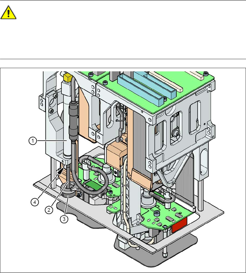
2.5.3 Safety instructions for manually moving the Z axis at the TwinStar
CAUTION
RISK OF CRUSHING AT THE TwinStar 2
NEVER move the Z axis down with your hand at the buffer of the return unit. The powerful spring
force of the cylinder creates a risk of injury to your fingers due to the buffer springing back. The
same applies inside the TwinStar when the piston rod springs back into its starting position.
2
Fig. 2.5 - 2 Risk of crushing from the return unit on the TwinStar
(1) Return unit, compressed air cylinder
(2) Piston rod
(3) Buffer of the return unit
(4) Risk of crushing to fingers
User manual SIPLACE X-series Operational safety
From software version SR.70x.xx 01/2011 EN edition Safety instructions for operating the machine
67
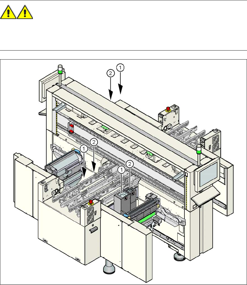
2.5.4 Safety instructions for the TwinStar component cameras during
a placement head change
WARNING 2
When the placement head is changed from the TwinStar to the SpeedStar, the TwinStar's com-
ponent cameras (stationary, P&P, type 33, 55 x 45, and type 25, 16 x 16) must be removed, oth-
erwise the SpeedStar will collide with the camera housings.
2
Fig. 2.5 - 3 Safety instructions for the TwinStar vision modules during a placement head change
(1) Assembly position for the component camera (stationary, P&P, type 33, 55 x 45) with refer-
ence to the X3
(2) Assembly position for the component camera (stationary, P&P, type 25, 16 x 16) with refer-
ence to the X3