00196504-02_UM_X-Serie_SR70X_EN.pdf - 第143页
User manual SIPLACE X-series Technical data for the machine From software version SR.70x.x x 01/2011 EN edition Gantry system 143 3.6.1.4 Position of the gantries for the X2 machine 3 Fig. 3.6 - 4 Position of the gantrie…
Technical data for the machine User manual SIPLACE X-series
Gantry system From software version SR.70x.xx 01/2011 EN edition
142
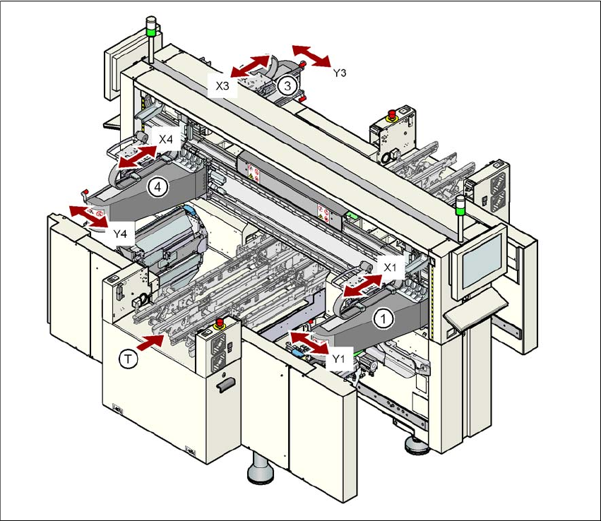
3.6.1.3 Position of the gantries for the X3 machine
3
Fig. 3.6 - 3 Position of the gantries on the X3 machine
a, d, f (gantry 1, gantry 3, gantry 4)
X1 X axis, gantry 1
Y1 Y axis, gantry 1
X3 X axis, gantry 3
Y3 Y axis, gantry 3
X4 X axis, gantry 4
Y4 Y axis, gantry 4
(T) Direction of PCB transport
Placement area 2
Placement area 1
User manual SIPLACE X-series Technical data for the machine
From software version SR.70x.xx 01/2011 EN edition Gantry system
143
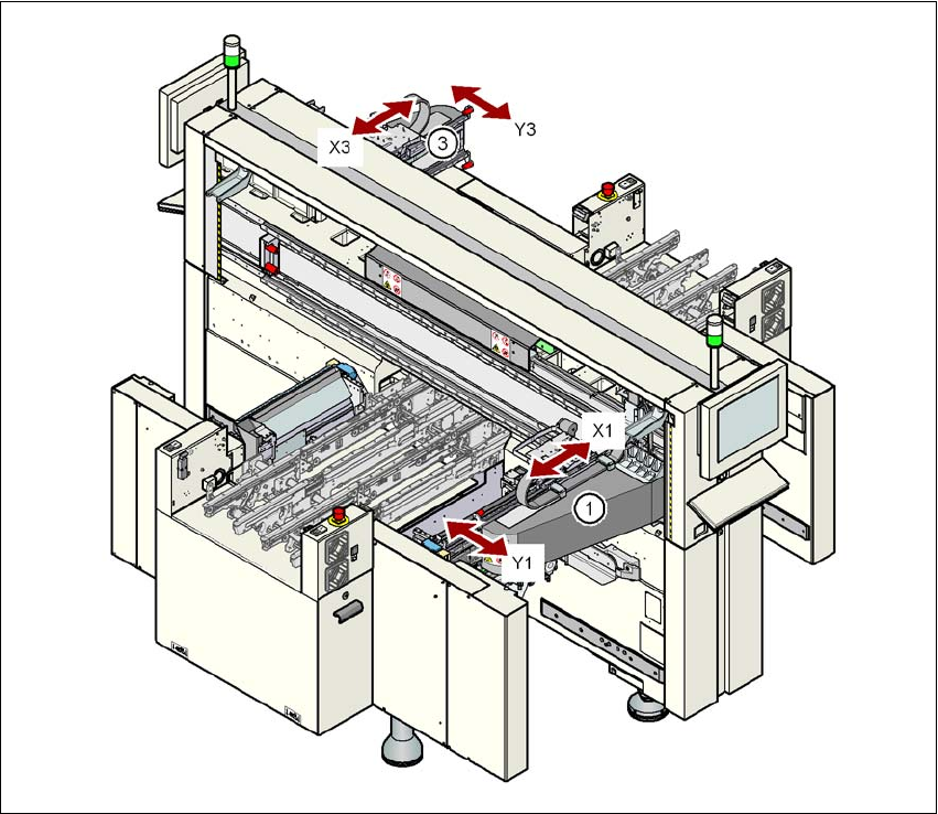
3.6.1.4 Position of the gantries for the X2 machine
3
Fig. 3.6 - 4 Position of the gantries on the X2 machine
a, d (gantry 1, gantry 3)
X1 X axis, gantry 1
Y1 Y axis, gantry 1
X3 X axis, gantry 3
Y3 Y axis, gantry 3
(T) Direction of PCB transport
The gantry system consists of two functional groups
–X axis and
–Y axis
Placement area 2
Placement area 1
Technical data for the machine User manual SIPLACE X-series
Gantry system From software version SR.70x.xx 01/2011 EN edition
144
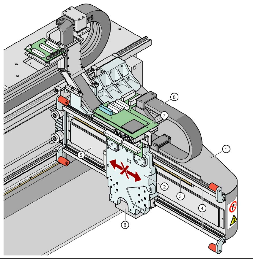
3.6.2 Structure of the X axis
3
Fig. 3.6 - 5 Structure of the X axis
(1) Gantry arm
(2) Head mount with X-axis linear motor (primary part)
(3) Linear distance measuring system
(4) Guide system
(5) Permanent magnet (secondary part of the X-axis linear motor)
(6) Sub-gantry camera
(7) Head boards
(8) Cable and hose carrier