00196504-02_UM_X-Serie_SR70X_EN.pdf - 第135页
User manual SIPLACE X-series Technical data for the machine From software version SR.70x.x x 01/2011 EN edition Placement head 135 3.5.2.9 T echnical dat a 3 CPP head: optical ce ntering with the high-resolution compo- n…
Technical data for the machine User manual SIPLACE X-series
Placement head From software version SR.70x.xx 01/2011 EN edition
134
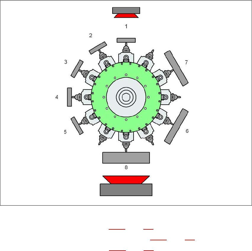
3.5.2.8 MultiStar in extended Pick&Place mode
In this mode, the MultiStar can place the entire component range from 01005 to 50 x 40 mm². The
large component is picked up last, optically centered and placed as the first component.
3
Fig. 3.5 - 8 MultiStar - mixed mode
K_BE Small component (see table 3.5 - 1, page 131)
M_BE_2 Medium-sized component, type 2 (see table 3.5 - 1
, page 131)
G_BE Large component (see table 3.5 - 1
, page 131)
Type 30/38 Component camera, type 30 or type 38
Type 33 Stationary component camera, type 33
1 ... 8 Order in which the components are picked up
3
Adjacent segments of the CPP head cannot pick up type M_BE_2 and G_BE components if the
diagonals of these components are more than 39.8 mm long.
In pure Pick&Place mode, only one large component is placed in one cycle. In this case, the CPP
head acts as a Pick&Place head.
Type 30/
K_BE
G_BE
Type 33
M_BE_2
User manual SIPLACE X-series Technical data for the machine
From software version SR.70x.xx 01/2011 EN edition Placement head
135
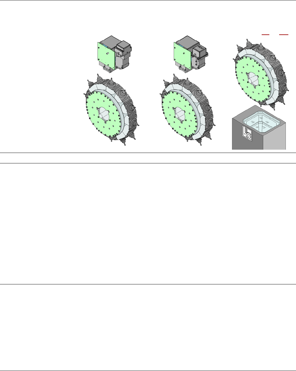
3.5.2.9 Technical data
3
CPP head: optical centering
with the high-resolution compo-
nent camera, type 30,
27 x 27, digital
CPP head: optical centering
with the high-resolution
component camera, type 38,
16 x 16, digital
CPP head: optical centering
with the stationary compo-
nent camera, type 33, 55 x
45, digital
(see Section 6.7
, S. 406)
Range of components
a
01005
b
- 27 x 27 mm² 01005
b
- 16 x 16 mm² 0402 - 50 x 40 mm²
Component specification
max. height 8.5 mm / 6 mm
c
8.5 mm / 6 mm
c
11.5 mm
min. lead pitch 0.3 mm 0.25 mm 0.3 mm
min. lead width 0.15 mm 0.1 mm 0.15 mm
min. ball pitch 0.25 mm for components < 18
x 18 mm²
0.35 mm for CO ≥ 18 x 18 mm²
0.25 mm 0.35 mm
min. ball diameter 0.14 mm for components < 18
x 18 mm²
0.2 mm for CO ≥ 18 x 18 mm²
0.14 mm 0.2 mm
min. dimensions 0.4 x 0.2 mm² 0.4 x 0.2 mm² 1.0 x 0.5 mm²
max. dimensions 27 x 27 mm² 16 x 16 mm² 50 x 40 mm²
max. weight 4 g 4 g 8 g
Set-down force
in current sensor mode
(reduced placement
-rate)
1 N ... 3.0 N ± 0.5 N
in light barrier mode 2.2 N + 1.2 N - 0.5 N
in high-speed mode in
current sensor -mode
2.2 N ± 0.5 N
in current sensor mode
(reduced placement
-rate)
3.0 N ... 10.0 N ± 15%

Technical data for the machine User manual SIPLACE X-series
Placement head From software version SR.70x.xx 01/2011 EN edition
136
Nozzle types 20xx, 28xx 20xx 20xx, 28xx
X/Y accuracy
d
± 41 µm/3σ
± 55 µm/4σ
± 41 µm/3
± 55 µm/4
± 34 µm/3σ
± 45 µm/4σ
Angular accuracy ± 0.4°/3σ
e
± 0.5°/4σ
e
± 0.4°/3
f
± 0.5°/4
f
± 0.2°/3σ
± 0.3°/4σ
± 0.5°/3σ
g
± 0.7°/4σ
g
± 0.5°/4
g
± 0.7°/4
g
Illumination levels 5 5 6
Possible illumination -level
settings
256
5
256
5
256
6
a) Please note that the component range that can be placed is also affected by the pad geometry, the customer-specific stan-
dards and the packaging tolerances.
b) 01005 components: camera type 30; type 38 camera recommended for high quality requirements.
c) CPP head in low mounting position: stationary camera not applicable
d) The accuracy value was measured using the vendor-neutral IPC standard.
e) For components between 6 x 6 mm² and 27 x 27 mm².
f) For components between 6 x 6 mm² and 16 x 16 mm².
g) For components smaller than 6 x 6 mm².