00196504-02_UM_X-Serie_SR70X_EN.pdf - 第168页
Technical data for the machine User manual SIPLACE X-series Vision system From software vers ion SR .70x.xx 01/2011 EN edition 168 3.8.6 Fiducial criteria 3 3.8.7 Ink spot criteria 3 Locate 2 fiducials Locate 3 fiducials…
User manual SIPLACE X-series Technical data for the machine
From software version SR.70x.xx 01/2011 EN edition Vision system
167
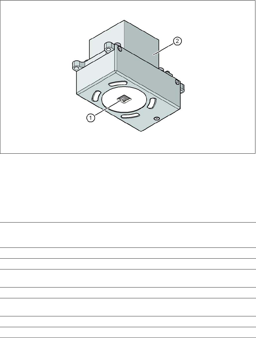
3.8.5 PCB camera, type 34, digital
3.8.5.1 Structure
3
Fig. 3.8 - 6 PCB camera, type 34, digital
(1) PCB camera lens and illumination
(2) Camera amplifier
3.8.5.2 Technical data
3
PCB fiducials up to 3 (subpanels and multiple panels)
up to 6 for the Long board option (Optional PCB fiducials are
output by the optimization).
Local fiducials up to 2 per PCB (may be of different type)
Library memory up to 255 fiducial types per subpanel
Image analysis edge detection method (Singular feature) based on grayscale
values
Method of illumination front-illumination (3 levels, programmable as required)
Detection time per fiducial
/bad fiducial
20 ms - 200 ms
Field of vision 5.78 x 5.78 mm²
Distance from the focus plane 28 mm

Technical data for the machine User manual SIPLACE X-series
Vision system From software version SR.70x.xx 01/2011 EN edition
168
3.8.6 Fiducial criteria
3
3.8.7 Ink spot criteria
3
Locate 2 fiducials
Locate 3 fiducials
X-/Y-position, rotation angle, mean PCB distortion
in addition: shear, distortion in X- and Y-direction separately
Fiducial shapes synthetic fiducials: circle, cross, square, rectangle, rhombus,
circular, square, and rectangular contours, double cross
any pattern
Fiducial surface
copper
tin
without oxidation and solder resist
warp 1/10 of structure width, both with good contrast to
environment
Dimensions of synthetic fiducials
min. X/Y size for circle and rectangle:
min. X/Y size for annulus and rectangle:
min. X/Y size for cross:
min. X/Y size for double-cross:
min. X/Y size for rhombus:
min. frame width for annulus and rectangle:
min. bar width / bar distance for cross, double-cross:
max. X/Y size for all fiducial shapes:
max. bar width for cross, double-cross:
min. tolerances, general:
max. tolerances, general:
0.25 mm
0.3 mm
0.3 mm
0.5 mm
0.35 mm
0.1 mm
0.1 mm
3 mm
1.5 mm
2% of nominal dimension
20% of nominal dimension
Dimensions of patterns
min. size
max. size
0.5 mm
3 mm
Fiducial environment clearance around reference fiducial not necessary if there is no
similar fiducial structure in the search area.
Methods - synthetic fiducial recognition method
- mean grayscale value
- histogram method
- template matching
Shapes and sizes of fiducials/
structures for
synthetic fiducials
other methods
for dimensions of synthetic fiducials, see Section 3.8.6
Fiducial
criteria, page 168.
min. 0.3 mm
max. 5 mm
Masking material good coverage
Recognition time depends on the method: 20 ms - 0.2 s

User manual SIPLACE X-series Technical data for the machine
From software version SR.70x.xx 01/2011 EN edition X feeder modules
169
3.9 X feeder modules
Important features for the SIPLACE X feeder modules are the high precision of the pick-up posi-
tion, online programmability, status displays on an LCD display and easy handling when changing
feeder modules during the placement process. The power supply to the feeder modules is con-
tactless and uses an inductive interface on the component trolley docking unit. Each feeder mod-
ule communicates with the feeder control unit (FCU) on the component trolley docking unit via two
optoelectronic channels (optical fiber). These two interfaces create the EDIF module (energy and
data interface, see point 2 in Fig. 3.9 - 1
, page 172). The feeder module control unit is, in turn,
connected to the machine's control unit via the CAN bus.
3.9.1 Tape feeder modules for the SIPLACE X-series
3.9.1.1 Tape material
The possible tape widths range from 8 mm to 88 mm. The tape material is blister or paper. Com-
ponent tapes with a permanently adhesive cover foil (PSA foil) can also be processed. This will
require the "PSA Kit" option.
The design of the tape feeder modules was based on the following tape standards:
DIN EN 60286-3 (12/1998) / IEC 60286-3 (12/1997)
JIS C 0806-3 (1999)
ANSI/EIA 481-C (10/2003) 3
The overall height of the blister tapes depends on the tape width, and must not exceed the follow-
ing maximum values:
For 8 mm paper tapes, the paper thickness must not exceed 1.6 mm. The length of a component
-pocket in the direction of travel must not exceed 51 mm.
PSA Kit Item no.
8 mm X PSA Kit 00141224-xx
12 mm X PSA Kit 00141225-xx
16 mm X PSA Kit 00141227-xx
Tape width Overall height of the blister tapes
8 mm max. 3.5 mm
12 mm max. 6.5 mm
16 mm and wider max. 25 mm