00196504-02_UM_X-Serie_SR70X_EN.pdf - 第306页
Tasks on the machine User manual SIPLACE X-series The user interface From software version SR.70x.xx 01/2011 EN edition 306 (Green) S tarts the con text-sensitive hel p for the curr e nt view . All the controls in the vi…
User manual SIPLACE X-series Tasks on the machine
From software version SR.70x.xx 01/2011 EN edition The user interface
305
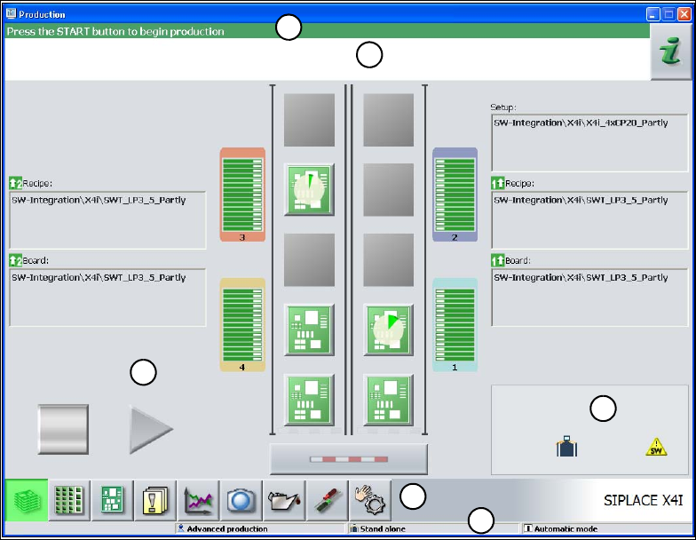
5.5 The user interface
The -user interface is divided into the areas described below.
By way of example, here you can see the user interface in the "Basic production" view for the X4I
machine.
5
Fig. 5.5 - 1 Components of the user interface in the "Basic production" view (in the example of the SIPLACE X4I)
(1) Title bar
(2) Status field (status and error display)
(3) Processing area / display area
(4) Toolbar
(5) Info line
(6) Displays modified configurations and additional options, e.g. barcode mode
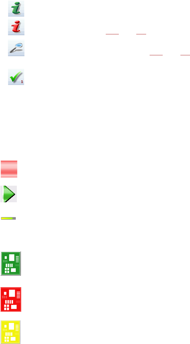
5.5.1 Status field
The status field displays the current machine status, the most recent error and the associated ac-
tion required.
The following symbols appear on the right-hand side of the status field, depending on the status:
1
2
3
4
5
6
Tasks on the machine User manual SIPLACE X-series
The user interface From software version SR.70x.xx 01/2011 EN edition
306
(Green) Starts the context-sensitive help for the current view. All the controls in the view are briefly
explained.
(Red) Starts the help system that lists possible causes of the current error and suggests ways to
eliminate them (see section 5.6.1
, page 313).
Opens a dialog box containing the source of the error, the error message text and the date and
time at which the error occurred (see section 5.6.1
, page 313). You can also call up help about
the current error from here.
Clears the currently-displayed error from the status field.
5.5.2 Display and processing area
This area contains the buttons for setting / starting functions, general information about the PCB,
set-up, batch and other notes.
Animated objects identified by different colors are used to display operations or statuses (e.g. pro-
cessing, location empty, etc.).
The "Production" view (main view) signals certain operating statuses (processing, error, etc.).
Pause processing. Pauses the current placement process.
Resume processing. Starts or resumes placement of the PCBs.
Progress bar
Displays the how far the placement process has progressed for each PCB.
PCB in progress
The PCB is in the system and is being processed. The PCB symbol appears dark green in the
form of a button.
Processing of PCB canceled
If processing was cancel, the PCB symbol turns red.
PCB must be checked
If the PCB is on the output belt and the status of the PCB has to be checked by the operator, the
PCB symbol turns yellow.
User manual SIPLACE X-series Tasks on the machine
From software version SR.70x.xx 01/2011 EN edition The user interface
307
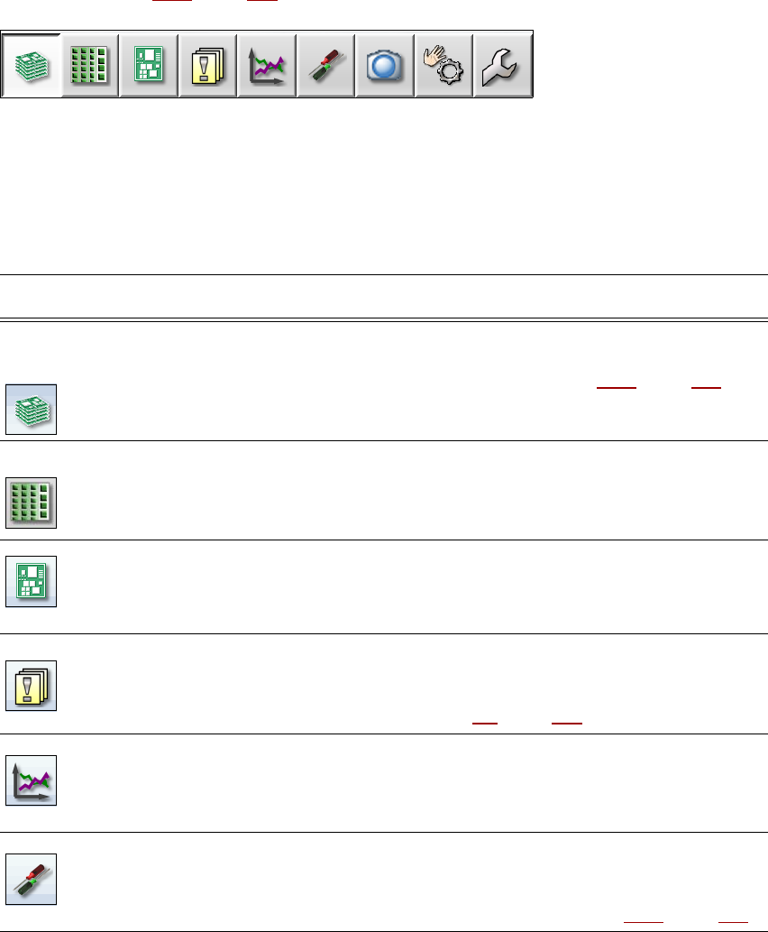
5.5.3 Toolbar
The toolbar contains buttons for the main station software functions.
This allows you to switch the user interface to other views and to use other functions from these
views (see section 5.5.5
, page 310).
5
Fig. 5.5 - 2 Toolbar
The buttons vary according to the configuration and which operator level is set. Some views are
only available at the higher operator levels.
The following table briefly describes the buttons and their main functions.
5
Symbol View Description
Basic production
(main view)
Displays the machine status for the -tasks most frequently carried
out during basic production.
Displays the operating statuses, see section 5.5.2
, page 306.
Displays locations, set-up name, batch name, changes made to the
configuration and additional options.
Feeders, compo-
nents and noz-
zles
The set-up can be called for each of the 4 locations individually.
For checking and setting up feeders, components and nozzles.
For teaching component shapes and component pocket shapes.
Displays the fill level.
PCBs Displays the PCB and placement positions list.
For checking and setting up the PCBs and components.
For teaching fiducials.
Messages Displays messages about current and previous events. There are
different types of message. A table can be called up for track errors,
conveyor errors, machine errors, general errors and concatenated
error messages (see section 5.6
, page 312).
Statistics Displays statistics about output, quality and rejected materials.
Displays the output of the machines and PCBs.
Starts the OIS (Operator Information System), for further informa-
tion, see the OIS documentation.
Settings Contains all the settings and options.
For setting the operator level and language of the user interface.
For displaying and changing machine settings, user settings, ma-
chine options and software options, see section 5.5.5
, page 310.