00196504-02_UM_X-Serie_SR70X_EN.pdf - 第171页
User manual SIPLACE X-series Technical data for the machine From software version SR.70x.xx 01/2011 EN edition X feeder modules 171 3.9.1.5 T ape feeder module shapes for the SIPLACE X-series In general, the t ape feeder…

Technical data for the machine User manual SIPLACE X-series
X feeder modules From software version SR.70x.xx 01/2011 EN edition
170
3.9.1.2 Tape reel diameter
The tape reel diameter may be up to 19" (483 mm) for all feeder modules. A list of the maximum
tape reel diameters in relation to the PCB conveyor height can be found in Section 3.10.8.2
, page
206
.
3.9.1.3 Manual removal of tantalum capacitors that were not picked up by the
operator
To ensure that tantalum capacitors do not cause the tape material to burn when it is cut as a result
of pick-up errors, the user interface has been extended to include the "Remove component from
tape in the event of a pick-up error" option. This option must be enabled in SIPLACE Pro. On the
placement machine, the component that was not picked up is paced forward again until it is ready
for removal from the component tape. The track is deactivated and the operator is sent an error
message to remind him to pick up the tantalum component from the tape.
If an alternative track is available, the machine continues placing. The operator is able to stop the
machine, however, and pick up the tantalum component.
If no alternative track is available and it is not possible to continue placement with other compo-
nents, the machine will stop. At this point, the operator can again remove the tantalum component
and acknowledge the error. Once the operator has restarted the machine, placement is continued
and components are picked up from the track that is now enabled once more.
PLEASE NOTE 3
This software function is also a good idea for expensive components. Please follow the safety
instructions for capacitors based on powdered metal (see Section 2.5.2, page 64).
3.9.1.4 Feeding capacity for the X tape feeder modules
3
Tape feeder
module
Max. number of feeder modules
SIPLACE X4I
Max. number of feeder modules
SIPLACE X4, X3, X2
8 mm X 148 160
2x8 mm X 74 80
12 mm X 74 80
16 mm X 48 52
24 mm X 48 52
32 mm X 36 40
44 mm X 28 32
56 mm X 22 24
72 mm X - 20
88 mm X - 16

User manual SIPLACE X-series Technical data for the machine
From software version SR.70x.xx 01/2011 EN edition X feeder modules
171
3.9.1.5 Tape feeder module shapes for the SIPLACE X-series
In general, the tape feeder modules from the X-series are approx. 587 mm long and approx. 200
mm high. The width and the number of locations that it fills on the component table are listed in
the following table.
3
The maximum height of any edges protruding over the top edge of the tape pocket is 3 mm.
Since the feeder modules do not have any raised flaps and are firmly anchored to the component
table, the risk of a head crash is minimized.
Tape feeder
modules
Feeder module width in
millimeters
Feeder module locations
required on the component
table
8 mm X 10.8 1
2x8 mm X 22.9 2
12 mm X 22.6 2
16 mm X 34.4 3
24 mm X 34.4 3
32 mm X 46.2 4
44 mm X 58.0 5
56 mm X 69.8 6
72 mm X 81.6 7
88 mm X 105.2 9
Technical data for the machine User manual SIPLACE X-series
X feeder modules From software version SR.70x.xx 01/2011 EN edition
172
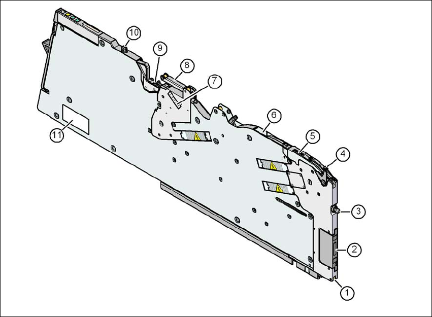
3.9.1.6 Design of the tape feeder module for the SIPLACE X-series
The two following diagrams show the design of the tape feeder module for the X-series with ref-
erence to the 8 mm X tape feeder module.
3
Fig. 3.9 - 1 8 mm X tape feeder module - front view
(1) Locking roller (the locking latch of the component table locks the feeder module in its end po-
sition with the locking roller.)
(2) EDIF (energy and data interface)
(3) "Front" centering pin
(4) Lever for raising the pick-up window in order to thread in and remove the component tape
(5) Pick-up window
(6) Exit from the tape guide channel
(7) Setting the cover foil tension
(8) Cover foil rocker
(9) Cover foil packing wheels
(10) "Back" centering pin
(11) Rating plate