00196504-02_UM_X-Serie_SR70X_EN.pdf - 第132页
Technical data for the machine User manual SIPLACE X-series Placement head From software version SR.70x.xx 01/2011 EN edition 132 3.5.2.5 MultiSt ar mounting positions on the machine 3.5.2.6 MultiSt ar in Collect&Pla…
User manual SIPLACE X-series Technical data for the machine
From software version SR.70x.xx 01/2011 EN edition Placement head
131
– TwinStar
3.5.2.3 Classification of the component range to be processed
3
3.5.2.4 MultiStar placement modes
The CPP head works in different placement modes according to the component class. The set-up
optimization selects the placement mode with the minimum cycle times. The following table illus-
trates the association between the component class and placement mode.
Tab. 3.5 - 2 Relationships between the component class and placement modes
3
3
Component
class
Component
size
Mounting position
a
for the CPP head
Component
height
CO camera type
Small compo-
nent
K_BE
01005
b
-
27 x 27 mm²
upper up to 8.5 mm
Head camera,
type 30
lower up to 6 mm
01005
b
-
16 x 16 mm²
lower up to 6 mm
Head camera,
type 38
Medium-sized
component, type
M_BE_1
< 27 x 27 mm²
upper
between 8.5 and
11.5 mm
Stationary CO
camera,
type 33
(see Section 6.7.1
,
page 406
)
lower not possible
Medium-sized
component, type
M_BE_2
between
27 x 27 mm²
and 32 x 32 mm²
upper 11.5 mm
lower not possible
Large compo-
nent
G_BE
between 32 x
32 mm² and
50 x 40 mm²
upper up to 11.5 mm Stationary CO
camera,
type 33
lower not possible
Tab. 3.5 - 1 Classification of the component range to be processed
a) Please follow the rules for the height of the mounting positions in section 3.5.2.2, page 130.
b) 01005 components: camera type 30; type 38 camera recommended for high quality requirements
Placement mode Component class
Small component Medium-sized
component
Large component
Collect&Place
mode
yes no no
Mixed mode yes yes no
Extended Pick&Place
mode
yes yes yes
Pure
Pick&Place mode
no no yes
Technical data for the machine User manual SIPLACE X-series
Placement head From software version SR.70x.xx 01/2011 EN edition
132
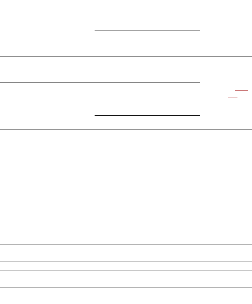
3.5.2.5 MultiStar mounting positions on the machine
3.5.2.6 MultiStar in Collect&Place mode
In this mode, the MultiStar processes small components.
3
Fig. 3.5 - 6 MultiStar - Collect&Place mode
K_BE Small component (see table 3.5 - 1, page 131)
Type 30/38 Component camera, type 30 or type 38
1 ... 12 Order in which the components are picked up
Placement machine Mounting position
a
CPP head
Maximum component
height
Vision camera
SIPLACE X4I lower only 6 mm Head camera
SIPLACE X4, X3, X2 lower 6 mm Head camera
upper 8.5 mm Head camera
upper only 11.5 mm
Stationary component
camera
Tab. 3.5 - 3 CPP head mounting positions on the machine
a) Please follow the rules for the height of the mounting positions in section 3.5.2.2, page 130.
Type 30/38
User manual SIPLACE X-series Technical data for the machine
From software version SR.70x.xx 01/2011 EN edition Placement head
133
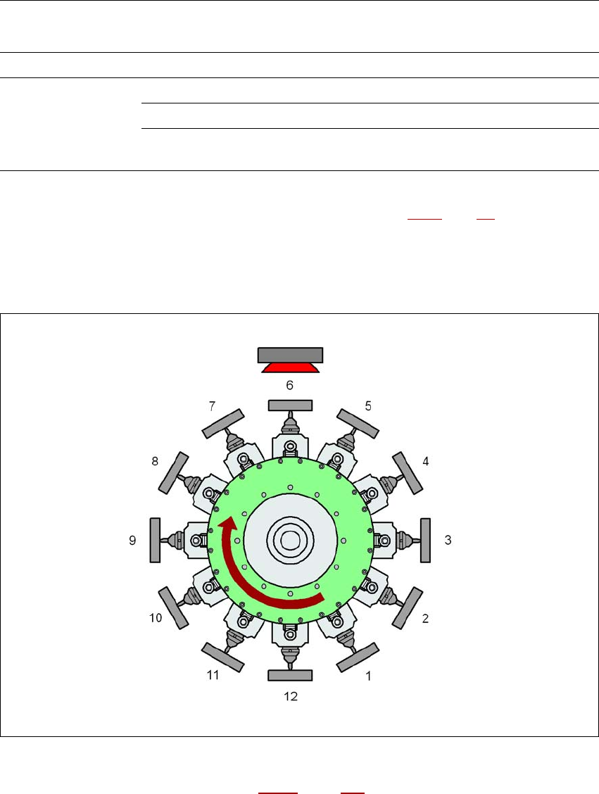
3.5.2.7 MultiStar in mixed mode
Small to medium-sized components are processed in this mode.
3
Fig. 3.5 - 7 MultiStar - mixed mode
K_BE Small component, see table 3.5 - 1, page 131
M_BE_1 Medium-sized component, type 1 (see table 3.5 - 1, page 131)
M_BE_2 Medium-sized component, type 2 (see table 3.5 - 1
, page 131)
Type 30/38 Component camera, type 30 or type 38
Type 33 Stationary component camera, type 33
1 ... 8 Order in which the components are picked up
1 ... 12 Order in which the components are picked up
3
Adjacent segments of the CPP head cannot pick up type M_BE_2 components if the diagonals of
the medium-sized component, type 2 (M_BE_2) is more than 39.8 mm long.
Type 30/38 Type 30/38
Type 33 Type 33
K_BE
M_BE_2
M_BE_1
K_BE