00196504-02_UM_X-Serie_SR70X_EN.pdf - 第410页
Station extensions User manual SIPLACE X-series Multicolor PCB camera, type 24, digital Fro m software version SR.70x.xx 01/2011 EN edition 410 6.8.2 T echnical data 6 6.8.3 Illumination methods The following illuminatio…
User manual SIPLACE X-series Station extensions
From software version SR.70x.xx 01/2011 EN edition Multicolor PCB camera, type 24, digital
409
6
6
6
6
6
6.8 Multicolor PCB camera, type 24, digital
6.8.1 Structure
Item no. 00119774-xx PCB camera, X-series, multicolor, type 24
6
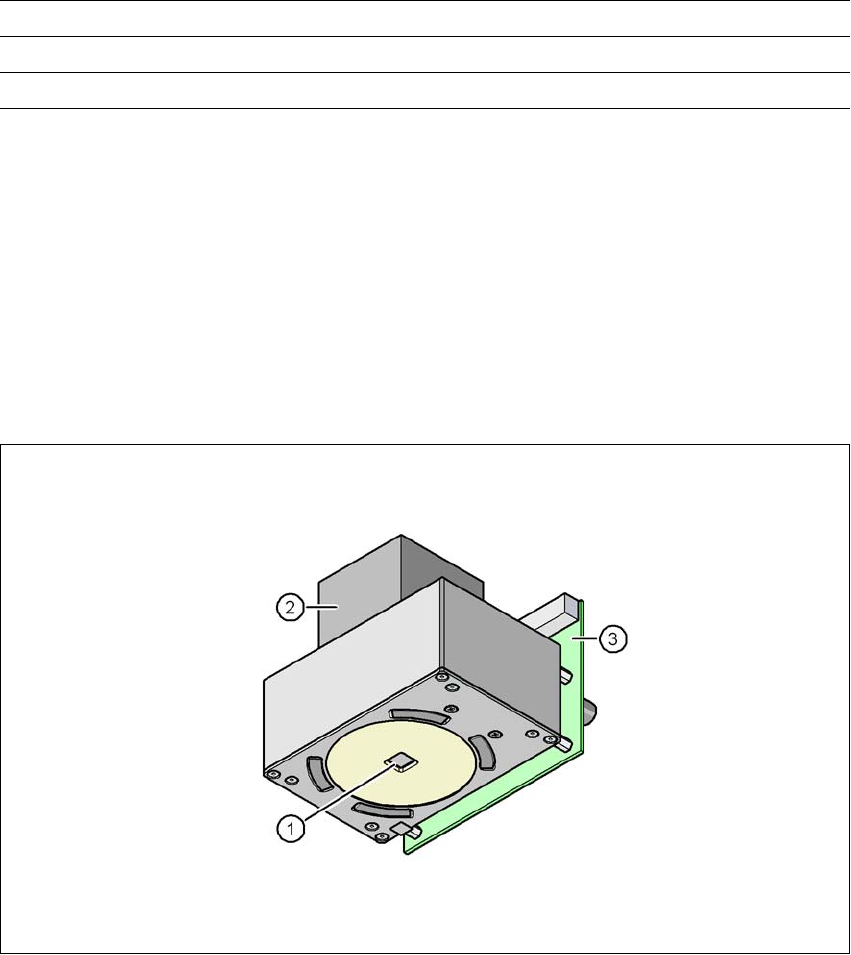
Fig. 6.8 - 1 Multicolor PCB camera, type 24, digital
(1) PCB camera lens and illumination
(2) Camera amplifier
(3) Illumination control
6
Min. ball diameter 0.14 mm
Field of vision 20.5 x 20.5 mm²
Method of illumination front-illumination (5 levels, programmable as required)

Station extensions User manual SIPLACE X-series
Multicolor PCB camera, type 24, digital From software version SR.70x.xx 01/2011 EN edition
410
6.8.2 Technical data
6
6.8.3 Illumination methods
The following illumination methods may be selected on the multicolor PCB camera:
– White lighting
This method of illumination is used for standard PCBs with tinned fiducials.
– Blue oblique lighting
This generally allows a considerable improvement in the contrast to be achieved with bright
fiducials on a light base material, such as ceramic or CEM. Even fiducials that are covered
with solder resist can be better detected on a light background.
– Infrared lighting
This method of illumination is particularly useful for fiducials that are covered with solder re-
sist, or for fiducials on flex material. It may even be possible to improve detection for silver/
platinum fiducials on ceramic; this should be determined in advance with a trial centering/
placement process.
6.8.4 Fiducials and ink spot criteria
Fiducials and ink spot criteria can be found in Sections 3.8.6 and 3.8.7, page 168.
Field of vision 5.7 x 5.7 mm²
Distance from the focus plane 28 mm
Method of illumination front-illumination (5 levels, programmable as required)
Fiducial size 0.3 mm to 2.5 mm edge length for a PCB conveyor tolerance of
± 1.0 mm
up to 3.0 mm edge length for a PCB conveyor tolerance of < 1.0
mm
Bad fiducial size 0.3 mm to 3.0 mm edge length
User manual SIPLACE X-series Station extensions
From software version SR.70x.xx 01/2011 EN edition 3D coplanarity sensor
411
6.9 3D coplanarity sensor
Item no. 00119919-xx 3D coplanarity sensor
6.9.1 Safety instructions
The sensor works with a semiconductor laser of wave length 660 nm (visible/red).
The maximum optical output is 60 mW.
The sensor is classified as laser class 3B.
– When operating the sensor, always follow the relevant regulations of VDE 0837 concerning
"Radiation safety for laser equipment" and German accident prevention regulation entitled
"Laser radiation" (BGV B2).
– Also follow the accident prevention regulations applicable in your country.
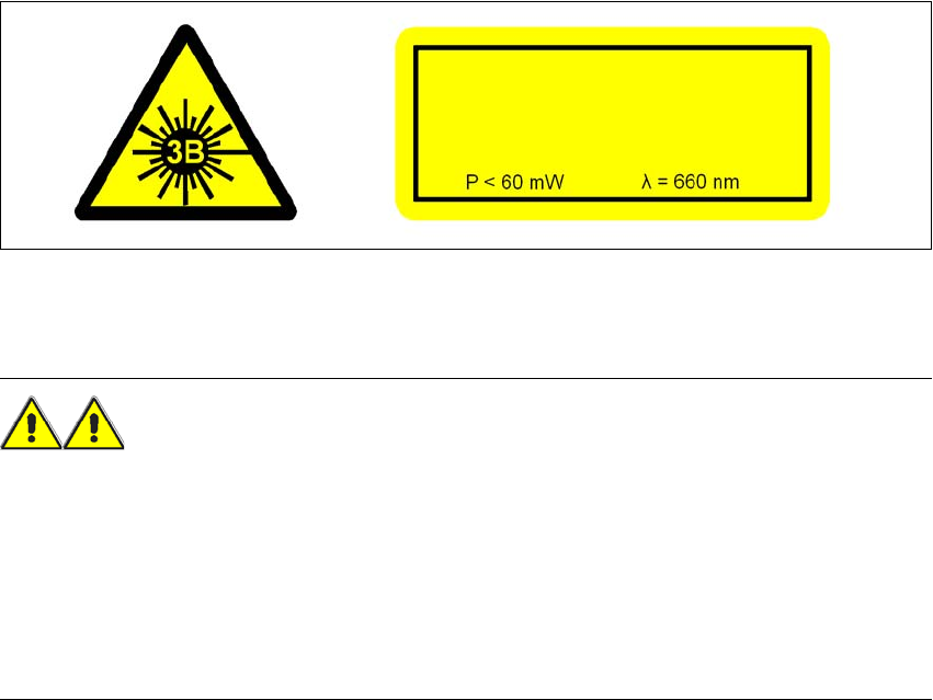
The following information plates are attached to the front and back of the sensor housing:
6
Fig. 6.9 - 1 Identification of laser class 3B for the sensor
The accessible laser radiation is dangerous to the eyes and, in special cases, even to the skin.
WARNING 6
– The 3D coplanarity sensor is integrated into the emergency stop circuit.
– The emergency stop circuit must not be disabled.
– The 3D coplanarity sensor may only be used inside the placement machine.
– Only authorized personnel may open the housing of the optical sensor.
– The sensors should always be sent to ASM Assembly Systems GmbH & Co. KG for repair
and servicing.
LASER RADIATION
DO NOT EXPOSE TO BEAM
LASER CLASS 3B
DIN EN 60825-1