00196504-02_UM_X-Serie_SR70X_EN.pdf - 第420页
Station extensions User manual SIPLACE X-series Magnetic pin support From software version SR.70x.xx 01/2011 EN edition 420 6.13 Magnetic pin support Item no. 001 19680-xx Magnetic pin su pport HS/HF/ X/D-series Wide boa…
User manual SIPLACE X-series Station extensions
From software version SR.70x.xx 01/2011 EN edition Siemens interface
419
The PCB is transported into the placement area until the laser light barrier triggers the stop signal
for the PCB conveyor. The lifting table with the PCB stops then moves up into a position in which
the PCB is not yet clamped and can still be moved by the conveyor belts. The two PCB stops are
level with the PCB, and the PCB supports (magnetic pins) are already in contact with the PCB.
The two conveyor belts move the PCB against the PCB stops and align them at the same time.
The lifting table then moves into its top end position, clamps the PCB and releases it from the PCB
stops so as not to affect the placement process. After the placement process, the lifting table and
PCB alignment are lowered and the PCB is moved on.
6
6.12 Siemens interface
Item no. 00116808-xx SIPLACE interface HF/X/D3
The conveyor interface on the placement machines from the X-series is configured to the SMEMA
standard. It is, however, still possible to use this interface in accordance with the Siemens stan-
dard. This is a significant benefit when an X-series machine is to be integrated into older SIPLACE
lines, in which case it would not be necessary to retrofit the older machines to conform to the
SMEMA standard.
Simply configure the conveyor interface of the X-series machines to the Siemens standard and
connect the machines using the associated interface cable.
More detailed information can be found in the Siemens conveyor interface retrofit instructions",
item no. 00194343-01.
Station extensions User manual SIPLACE X-series
Magnetic pin support From software version SR.70x.xx 01/2011 EN edition
420
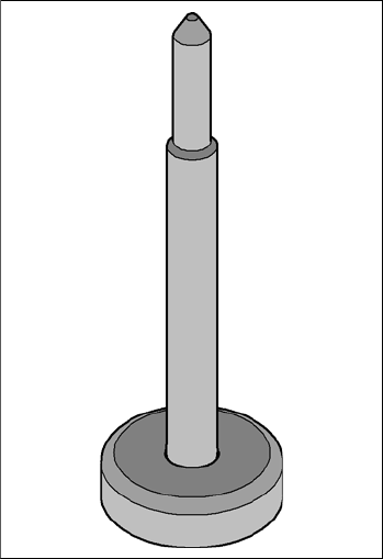
6.13 Magnetic pin support
Item no. 00119680-xx Magnetic pin support HS/HF/X/D-series
Wide boards tend to deflect during placement such that, under certain circumstances, the compo-
nents can no longer be placed with the desired accuracy. Highly curved PCBs also affect the
placement accuracy. This problem can be easily rectified by fitting magnetic pin supports on the
lifting table.
6
Fig. 6.13 - 1 Magnetic pin support

User manual SIPLACE X-series Station extensions
From software version SR.70x.xx 01/2011 EN edition Vacuum pump
421
6.14 Vacuum pump
Item no. 00119786-xx Vacuum pump, installation kit for X2, X3, X4
Item no. 00119787-xx Vacuum pump, X-series
Item no. 00119797-xx Vacuum pump, installation kit for X4I
6.14.1 Safety instructions for the vacuum pump
WARNING 6
The vacuum pump should have a separate fuse.
When connecting the vacuum pump, make sure that a ground wire is connected in addition
to the standard main power cable. A suitable grounding rail should therefore be provided in
the customer's network.
Pay particular attention to the safety instructions in the operating instructions provided.
6.14.2 Description
Every Collect&Place head has a separate vacuum generator that supplies the holding and place-
ment circuit with the vacuum that it needs. The vacuum generators for the placement heads work
on the Venturi principle. When combined with a vacuum pump, the compressed air consumption
can be greatly reduced on the SpeedStar (C&P20). The ongoing operating costs will fall in line
with the energy costs.
Type of machine
Placement head
configuration
Compressed air
consumption
a
without vacuum pump
Compressed air
consumption
a
with the vacuum
pump
b
SIPLACE X4I
SIPLACE X4
C&P20/C&P20/C&P20/C&P20 960 Nl/min 220 Nl/min
C&P20/C&P20/CPP/CPP 720 Nl/min 350 Nl/min
SIPLACE X4 C&P20/C&P20/CPP/TH 700 Nl/min 330 Nl/min
C&P20/C&P20/TH/TH 680 Nl/min 310 Nl/min
SIPLACE X3 C&P20/C&P20/C&P20 720 Nl/min 165 Nl/min
C&P20/C&P20/CPP 600 Nl/min 230 Nl/min
C&P20/C&P20/TH 580 Nl/min 210 Nl/min
SIPLACE X2 C&P20/C&P20 480 Nl/min 110 Nl/min
C&P20/CPP 360 Nl/min 175 Nl/min
C&P20/TH 340 Nl/min 155 Nl/min
a) Under normal atmospheric conditions at 20°C and 1013 hPa
b) Vacuum pump for the C&P20 head only