00196504-02_UM_X-Serie_SR70X_EN.pdf - 第137页
User manual SIPLACE X-series Technical data for the machine From software version SR.70x.x x 01/2011 EN edition Placement head 137 3.5.3 SIPLACE T winSt ar for high-precision IC placement 3 Fig. 3.5 - 9 SIPLACE T winStar…

Technical data for the machine User manual SIPLACE X-series
Placement head From software version SR.70x.xx 01/2011 EN edition
136
Nozzle types 20xx, 28xx 20xx 20xx, 28xx
X/Y accuracy
d
± 41 µm/3σ
± 55 µm/4σ
± 41 µm/3
± 55 µm/4
± 34 µm/3σ
± 45 µm/4σ
Angular accuracy ± 0.4°/3σ
e
± 0.5°/4σ
e
± 0.4°/3
f
± 0.5°/4
f
± 0.2°/3σ
± 0.3°/4σ
± 0.5°/3σ
g
± 0.7°/4σ
g
± 0.5°/4
g
± 0.7°/4
g
Illumination levels 5 5 6
Possible illumination -level
settings
256
5
256
5
256
6
a) Please note that the component range that can be placed is also affected by the pad geometry, the customer-specific stan-
dards and the packaging tolerances.
b) 01005 components: camera type 30; type 38 camera recommended for high quality requirements.
c) CPP head in low mounting position: stationary camera not applicable
d) The accuracy value was measured using the vendor-neutral IPC standard.
e) For components between 6 x 6 mm² and 27 x 27 mm².
f) For components between 6 x 6 mm² and 16 x 16 mm².
g) For components smaller than 6 x 6 mm².
User manual SIPLACE X-series Technical data for the machine
From software version SR.70x.xx 01/2011 EN edition Placement head
137
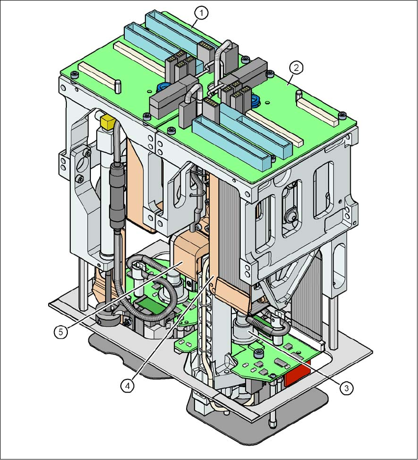
3.5.3 SIPLACE TwinStar for high-precision IC placement
3
Fig. 3.5 - 9 SIPLACE TwinStar for high-precision IC placement
3
(1) Pick&Place module 1 (P&P1) - the TwinStar consists of 2 Pick&Place modules
(2) Pick&Place module 2 (P&P2)
(3) DP axis
(4) Z axis drive
(5) Incremental distance measuring system for the Z axis
Technical data for the machine User manual SIPLACE X-series
Placement head From software version SR.70x.xx 01/2011 EN edition
138
3.5.3.1 Description
This sophisticated placement head consists of two placement heads of the same type coupled to-
gether (twin head). Both heads work using the Pick&Place principle. The TwinStar is suitable for
processing particularly complex or large components. Two components are picked up by the
placement head, optically centered on the way to the placement position and rotated into the nec-
essary placement angle. They are then placed gently and accurately onto the PCB with a con-
trolled blast of air.
New nozzles (type 5xx) have been developed for the TwinStar. It is also possible to fit an adapter
and then use type 4 nozzles for the Pick&Place head and type 8xx and 9xx nozzles for the
Collect&Place heads.
3.5.3.2 Technical data
Optical centering with Stationary P&P component camera
(type 33) 55 x 45, digital
(see Section 3.8.4
, page 166)
Stationary P&P component camera
(type 25) 16 x 16, digital
(see Section 6.6, page 404)
Range of components
a
0402 to SO, PLCC, QFP, BGA, spe-
cial components, bare dies, flip-
chips
0201 to SO, PLCC, QFP, sockets,
plugs, BGA, special components,
bare dies, flip-chips, shields
Component specification
b
max. height
min. lead pitch
min. lead width
min. ball pitch
min. ball diameter
min. dimensions
max. dimensions
max. weight
25 mm (higher available on request)
0.3 mm
0.15 mm
0.35 mm
0.2 mm
1.0 x 0.5 mm²
55 x 45 mm² (single measurement)
For use with two nozzles
50 x 50 mm² or
69 x 10 mm²
For use with one nozzle
85 x 85 mm² or
125 x 10 mm²
up to 200 x 125 mm² (with restric-
tions)
100 g
c
25 mm (higher available on request)
0.25 mm
0.1 mm
0.14 mm
0.08 mm
0.6 x 0.3 mm²
16 x 16 mm² (single measurement)
55 x 55 mm² (multiple measurement)
100 g
c