00196504-02_UM_X-Serie_SR70X_EN.pdf - 第414页
Station extensions User manual SIPLACE X-series 3D coplanarity sensor From software version SR .70x.xx 01/2011 EN edition 414 6.9.5 Restrictions – Lead or ball recognition can get worse if the surface is oxidized or glos…
User manual SIPLACE X-series Station extensions
From software version SR.70x.xx 01/2011 EN edition 3D coplanarity sensor
413
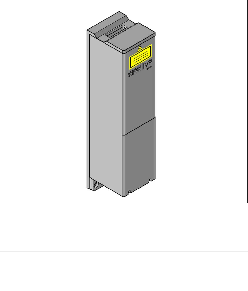
6.9.3 Description
The 3D coplanarity sensor no longer works with a dot-shaped laser light source. It now requires
a laser light line. The measuring process is based on the principle of triangulation. This makes it
possible to generate and analyze a height profile for a two-dimensional arrangement of compo-
nent connections, e.g. BGA, QFP, et. The analysis returns results for the coplanarity (placement
plane) and colinearity (placement line) of component leads or balls. The 3D coplanarity sensor
can be installed on SIPLACE X2, X3 and X4 placement machines.
6
Fig. 6.9 - 3 3D coplanarity sensor
6.9.4 Technical data
6
Components QFP, SO, BGA, gull-wing, plug
Accuracy
a
± 15 μm (3), ± 20 μm (4)
Maximum component size 50 x 50 mm²
Maximum component height 17 mm

Station extensions User manual SIPLACE X-series
3D coplanarity sensor From software version SR.70x.xx 01/2011 EN edition
414
6.9.5 Restrictions
– Lead or ball recognition can get worse if the surface is oxidized or glossy.
– The following components cannot be measured: a PLCC, SOJ, socket, chip, bare die,
Moulded, Melf, ECV, DPack, CCGA, screening plate, components which only have connec-
tions on the underside
6.9.6 Installation notes
Please note the following points if you are installing the 3D coplanarity sensor:
– The 3D coplanarity sensor can only be installed on SIPLACE machines that are equipped
with the A364 axis unit and the Box PC. It cannot be retrofitted on machines with the A363
axis unit.
– The 3D coplanarity sensor can only be used in conjunction with the TwinHead or high-force
head.
– The 3D coplanarity sensor cannot be set up if there is a Collect&Place head installed in this
placement area.
– Only one 3D coplanarity sensor can be installed at the following locations on each machine.
Package forms BGA
min. ball diameter
min. ball pitch
min. number of balls
400 m
800 m
6
Package forms Gullwing
min. lead width
b
min. ball pitch
min. number of balls
300 m
500 m
5
Max. plug size 120 x 20 mm²
Plug (Gullwing)
min. lead width
b
min. ball pitch
min. number of balls
300 m
500 m
5
Placement head type TwinHead (TH) or high-force head (HFH)
Laser protection class
3D coplanarity sensor
placement machine
3B
2
a) Per ball / lead
b) Please contact your local product manager in the case of smaller lead widths
User manual SIPLACE X-series Station extensions
From software version SR.70x.xx 01/2011 EN edition 3D coplanarity sensor
415
6
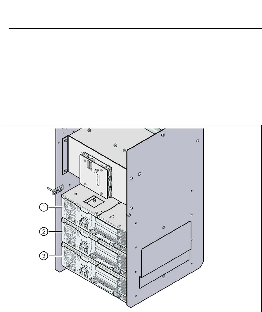
6.9.7 Analysis computer
A box PC acts as an analysis computer. It is housed together with the control computer and the
machine controller on the input side.
6
Fig. 6.9 - 4 Box PC for the 3D coplanarity sensor
(1) Control computer
(2) Machine controller
(3) Analysis computer for the 3D coplanarity sensor
Placement machine Location
SIPLACE X2 3
SIPLACE X3 3
SIPLACE X4 2 or 3