00196504-02_UM_X-Serie_SR70X_EN.pdf - 第198页
Technical data for the machine User manual SIPLACE X-series SIPLACE X-series component trolley From software version SR.70x.xx 01/2011 EN edition 198 3.10.1 Structure The component tro lley essentially consists of th e c…
User manual SIPLACE X-series Technical data for the machine
From software version SR.70x.xx 01/2011 EN edition SIPLACE X-series component trolley
197
3
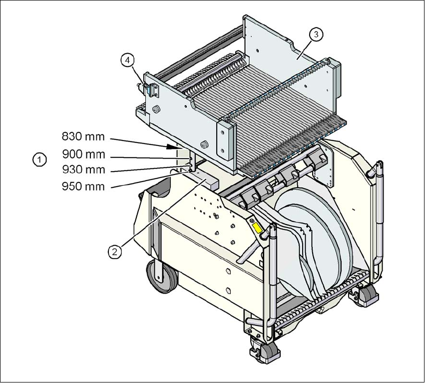
Fig. 3.10 - 2 Component trolley, SIPLACE X-series with a PCB conveyor height of 950 mm
3
(1) Holes for the PCB conveyor heights 900, 930 and 950 mm in the guide columns. For the
830 mm conveyor height, the component table lies on the block (2).
(2) Supporting block
(3) Component table
(4) Contact for switching the safety switch in the component trolley docking unit
Technical data for the machine User manual SIPLACE X-series
SIPLACE X-series component trolley From software version SR.70x.xx 01/2011 EN edition
198
3.10.1 Structure
The component trolley essentially consists of the chassis, the component table for holding the
feeder modules, the tape reel container and the waste tape container.
3
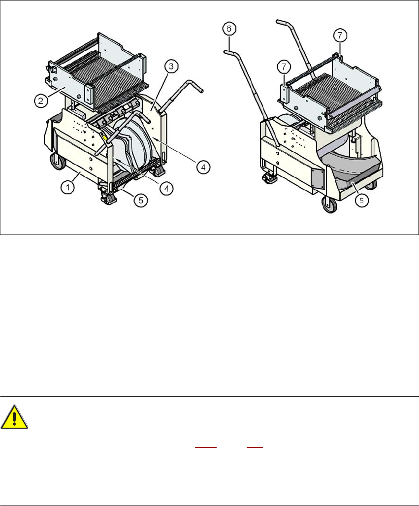
Fig. 3.10 - 3 Component trolley, SIPLACE X-series, front and back view
(1) Chassis
(2) Component table
(3) Tape container
(4) Slot for holding set-up lists
(5) Waste tape container
(6) Handle
(7) Hand guard
CAUTION 3
→ Follow the safety instructions in Section 5.8.2
, page 322, when you pull the waste tape con-
tainer out of the component trolley.
– The handles must only be used to push the component trolley.
→ Use a fork-lift if you want to transport the component trolley or lift it from the pallet.
User manual SIPLACE X-series Technical data for the machine
From software version SR.70x.xx 01/2011 EN edition SIPLACE X-series component trolley
199
3.10.2 Description
In the standard version, the tape reel container (item 3 in Fig. 3.10 - 3) holds tape reels up to 17"
(432 mm).
There are two 5 mm wide gaps (item 4 in Fig. 3.10 - 3
, page 198) on the left and right between the
tape container and the component trolley for holding set-up lists.
The pull-out waste tape container (item 5 in Fig. 3.10 - 3
, page 198) can be found beneath the
chassis. The cut waste tape travel down a chute into the waste tape container, which must be
emptied as it fills up.
The handles (item 6 in Fig. 3.10 - 3
, page 198) can be folded up or down.
PLEASE NOTE 3
All component trolleys, matrix tray changers or waffle-pack changers must be docked on the
machine in order to operate it. Fill any free locations with dummy feeder modules as described in
Section 2.6.5.1, page 84.
3.10.3 Technical data
3
3
Length x width 727 x 592 mm²
752 x 592 mm² with waste container
Height of the component table 819.5 mm for 830 mm PCB conveyor height
889.5 mm for 900 mm PCB conveyor height
919.5 mm for 930 mm PCB conveyor height
939.5 mm for 950 mm PCB conveyor height
PCB conveyor height 830 mm ± 15 mm (optional)
900 mm ± 15 mm (optional)
930 mm ± 15 mm (standard)
950 mm ± 15 mm (SMEMA option)
Height of the folded up handles 969 mm
Number of locations 40 (8 mm X tape feeder module)
Weight
without feeder modules
with feeder module at all locations
80.4 kg
139.6 kg
Tape reel diameter
standard
maximum
up to 432 mm (17")
483 mm (19")