00196504-02_UM_X-Serie_SR70X_EN.pdf - 第308页
Tasks on the machine User manual SIPLACE X-series The user interface From software version SR.70x.xx 01/2011 EN edition 308 5.5.4 Using the st ation sof tware within the views Most of the views that are ca lled from the …
User manual SIPLACE X-series Tasks on the machine
From software version SR.70x.xx 01/2011 EN edition The user interface
307
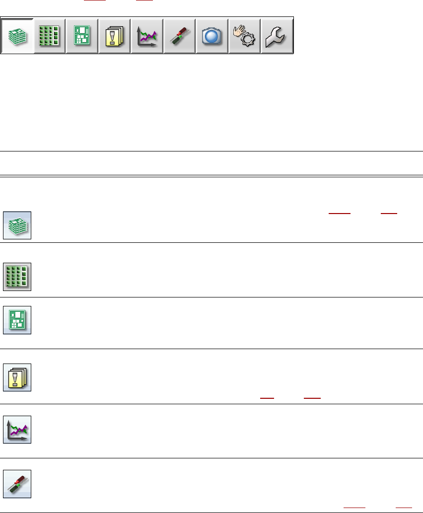
5.5.3 Toolbar
The toolbar contains buttons for the main station software functions.
This allows you to switch the user interface to other views and to use other functions from these
views (see section 5.5.5
, page 310).
5
Fig. 5.5 - 2 Toolbar
The buttons vary according to the configuration and which operator level is set. Some views are
only available at the higher operator levels.
The following table briefly describes the buttons and their main functions.
5
Symbol View Description
Basic production
(main view)
Displays the machine status for the -tasks most frequently carried
out during basic production.
Displays the operating statuses, see section 5.5.2
, page 306.
Displays locations, set-up name, batch name, changes made to the
configuration and additional options.
Feeders, compo-
nents and noz-
zles
The set-up can be called for each of the 4 locations individually.
For checking and setting up feeders, components and nozzles.
For teaching component shapes and component pocket shapes.
Displays the fill level.
PCBs Displays the PCB and placement positions list.
For checking and setting up the PCBs and components.
For teaching fiducials.
Messages Displays messages about current and previous events. There are
different types of message. A table can be called up for track errors,
conveyor errors, machine errors, general errors and concatenated
error messages (see section 5.6
, page 312).
Statistics Displays statistics about output, quality and rejected materials.
Displays the output of the machines and PCBs.
Starts the OIS (Operator Information System), for further informa-
tion, see the OIS documentation.
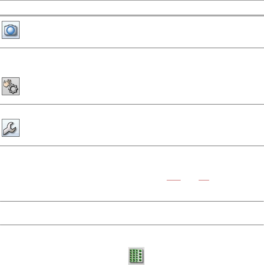
Settings Contains all the settings and options.
For setting the operator level and language of the user interface.
For displaying and changing machine settings, user settings, ma-
chine options and software options, see section 5.5.5
, page 310.
Tasks on the machine User manual SIPLACE X-series
The user interface From software version SR.70x.xx 01/2011 EN edition
308
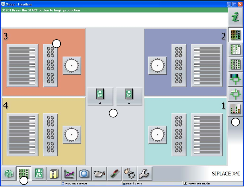
5.5.4 Using the station software within the views
Most of the views that are called from the toolbar (see section 5.5.3, page 307) have an additional
vertical toolbar for sub-views and functions on the right-hand side of the user interface.
NOTE
You will find a detailed description of the individual functions in the online help. 5
Example: "Feeders, components and nozzles" view
5
5
Click "Feeders, components and nozzles" on the toolbar.
The following view opens:
Live image during
placement
Displays the individual camera live images.
Only available at "Advanced production" operator level or higher:
displays and saves the vision dumps.
Check sensors
and functions
Contains information and functions for testing and diagnostics.
For setting the response to the machine Start button.
Only available at "Advanced production" operator level or higher:
for testing the complete reference run and functions of the C&P20A
head.
Single Functions and continuous runs. Each gantry is activated
separately.
Service Service tools.
Only available at "Machine service" operator level or higher.
For setting up and calibrating SIPLACE placement machine, down-
loading embedded software versions, calibrating and configuring
the complete machine.
Symbol View Description
User manual SIPLACE X-series Tasks on the machine
From software version SR.70x.xx 01/2011 EN edition The user interface
309
5
Fig. 5.5 - 3 User interface in the "Feeders, components and nozzles" view (with reference to the SIPLACE X4I)
(1) Toolbar ("Feeders, components and nozzles" button)
(2) Vertical toolbar in the "Feeders, components and nozzles" view.
(3) Processing area with 4 gantries
(4) Button for nozzle change to gantry 3
Click nozzle change from gantry 3 (button 4), for example, to check the nozzle configuration.
1
2
3
4