00196504-02_UM_X-Serie_SR70X_EN.pdf - 第334页
Tasks on the machine User manual SIPLACE X-series Setting up the feeder modules From software version SR.70x.xx 01/2011 EN edition 334 → Pull the cover foil at the side of the pick-up window forward and out und erneath t…
User manual SIPLACE X-series Tasks on the machine
From software version SR.70x.xx 01/2011 EN edition Setting up the feeder modules
333
5
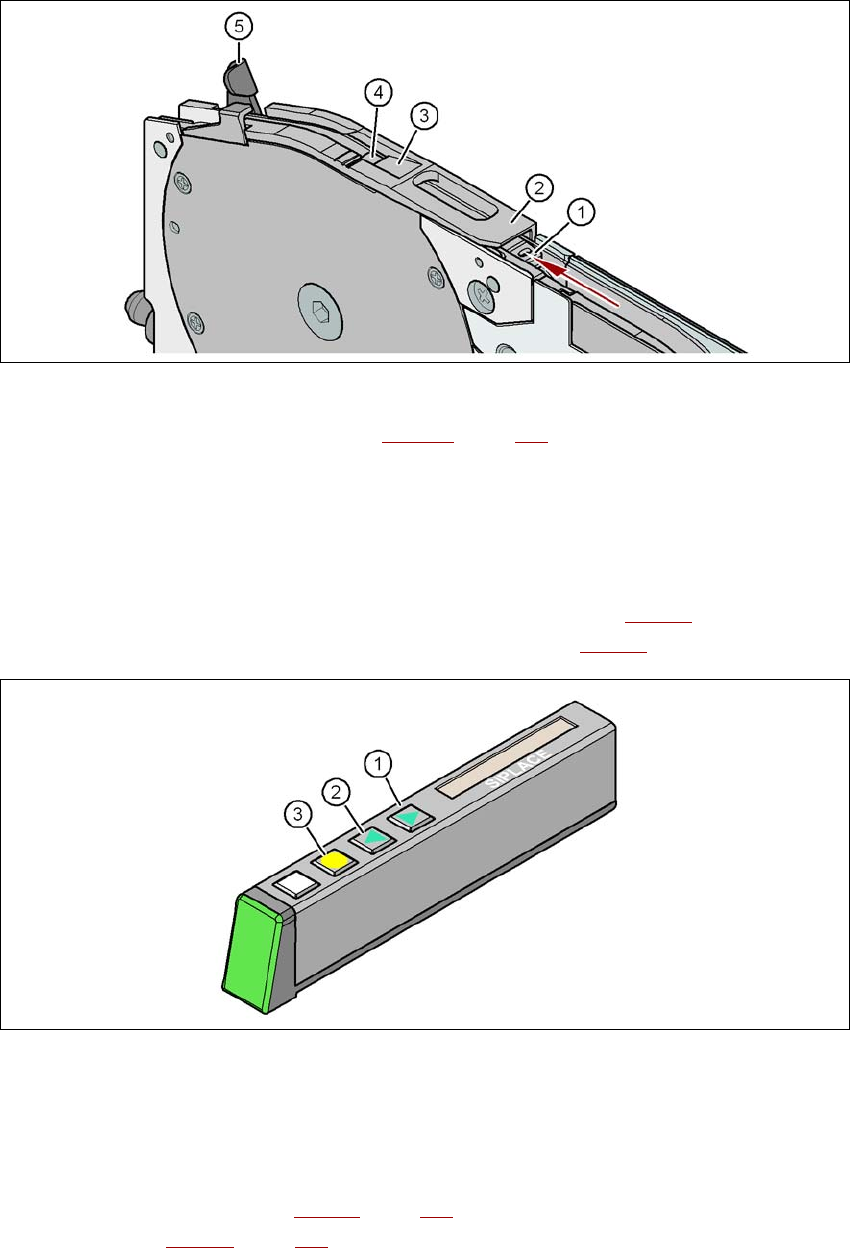
Fig. 5.10 - 5 Pick-up window on the tape feeder module
(1) Tape support, removable (see Section 5.10.4.4, page 335)
(2) Pick-up window
(3) Removal edge for the cover foil
(4) Component pick-up area
(5) Lever for raising and latching the pick-up window
→ On the operator panel, press the FORWARD button (item 1 in Fig. 5.10 - 6
) until the bend of
the cover foil is in the component pick-up area (item 4 in Fig. 5.10 - 5
).
5
Fig. 5.10 - 6 Operator panel of the feeder module
(1) FORWARD button for moving the component tape forward
(2) BACK button for moving the component tape back
(3) FOIL button for tensioning the cover foil
→ Push the lever (item 5 in Fig. 5.10 - 5
, page 333) forward in order to raise the pick-up window
(item 2 in Fig. 5.10 - 5
, page 333) into the first latching position.
Tasks on the machine User manual SIPLACE X-series
Setting up the feeder modules From software version SR.70x.xx 01/2011 EN edition
334
→ Pull the cover foil at the side of the pick-up window forward and out underneath the pick-up
window.
→ Fold the cover foil back until it lies against the pull-off edge (item 3 in Fig. 5.10 - 5
, page 333).
PLEASE NOTE 5
Do not lower the pick-up window until the cover foil is lying against the pull-off edge.
→ Push the lever (item 5 in Fig. 5.10 - 5
, page 333) back to lower the pick-up window.
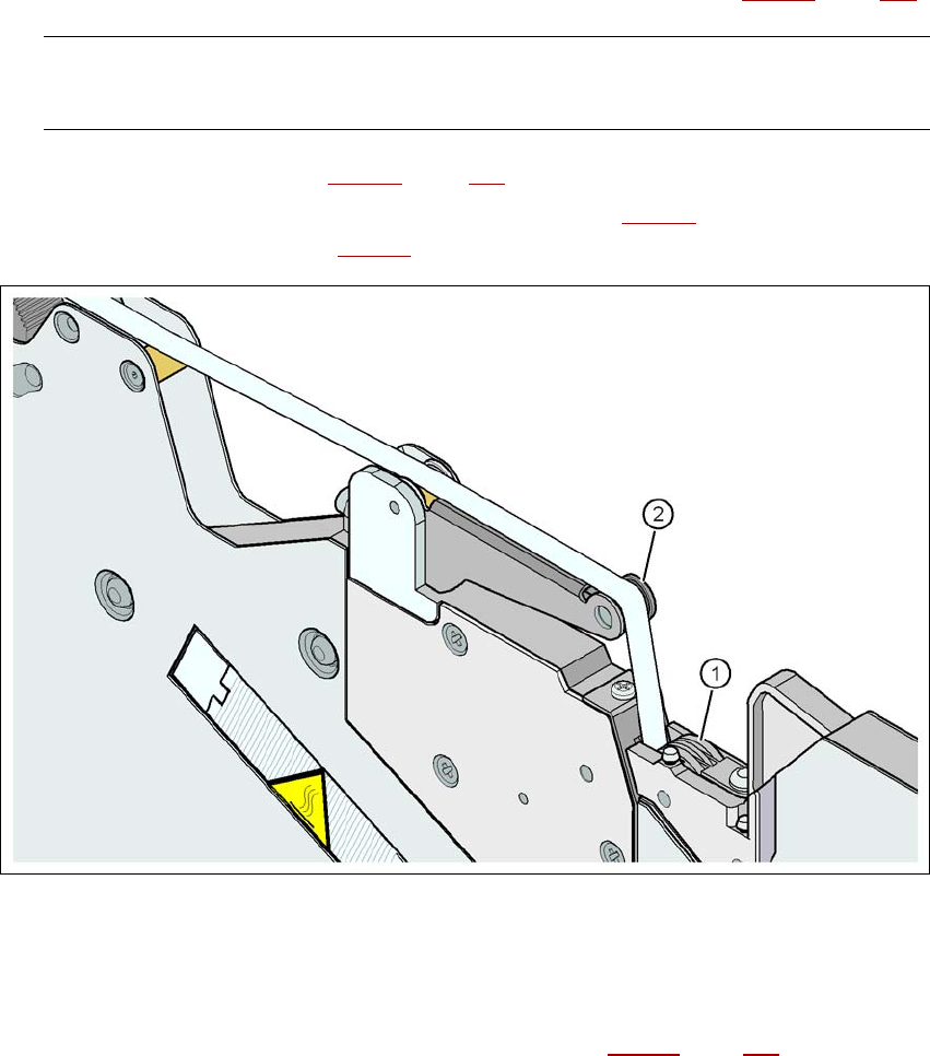
→ Guide the cover foil over the cover foil rocker (item 2 in Fig. 5.10 - 7
) until it reaches the foil
packing wheels (item 1 in Fig. 5.10 - 7
).
5
Fig. 5.10 - 7 Guiding the cover foil to the foil packing wheels
(1) Cover foil packing wheels
(2) cover foil
5
→ On the operator panel, press the FOIL button (item 3 in Fig. 5.10 - 6, page 333) until the cover
foil is tensioned. The cover foil rocker points down and stops the drive motor.
→ Cut the component tape flush with the front end of the feeder module.
User manual SIPLACE X-series Tasks on the machine
From software version SR.70x.xx 01/2011 EN edition Setting up the feeder modules
335
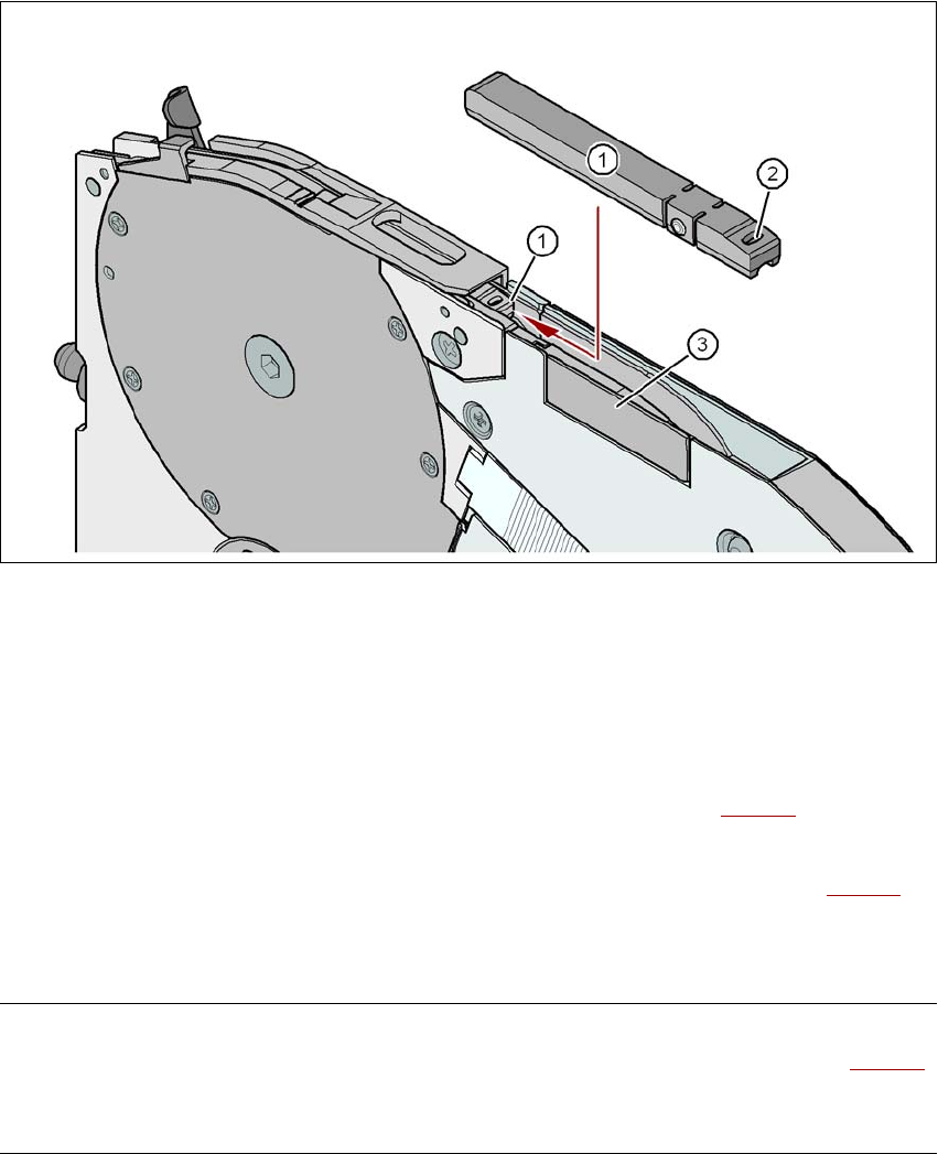
5.10.4.4 Tape support for 8 mm X tape feeder module
5
Fig. 5.10 - 8 8 mm X feeder module - tape support and splice sensor
(1) Tape support, removable
(2) Oval opening in the tape support
(3) Splice sensor installation location
The 8 mm X feeder module is equipped with a tape support (item 1 in Fig. 5.10 - 8
). It can easily
be removed if necessary.
→ Insert the tang of a watchmaker's screwdriver into the oval opening (item 2 in Fig. 5.10 - 8
) in
the tape support and pull the tape support out against the direction of travel of the tape.
→ When you insert the tape support, make sure that it engages in its desired position.
PLEASE NOTE 5
For all components size 0402 and smaller, always insert the tape support (item 1 in Fig. 5.10 - 8
)
into the 8 mm X feeder module. This will give you a constant Z pick up height and will minimize
the time needed to correct the pick up heights.