00196504-02_UM_X-Serie_SR70X_EN.pdf - 第356页
Station extensions User manual SIPLACE X-series Nozzle changer From softwar e version SR.70x.xx 01/2011 EN edition 356 6.1.1.6 Position of the nozzle changers for t he SIPLACE SpeedS tar on the X2 1 or 2 nozzle changers …
User manual SIPLACE X-series Station extensions
From software version SR.70x.xx 01/2011 EN edition Nozzle changer
355
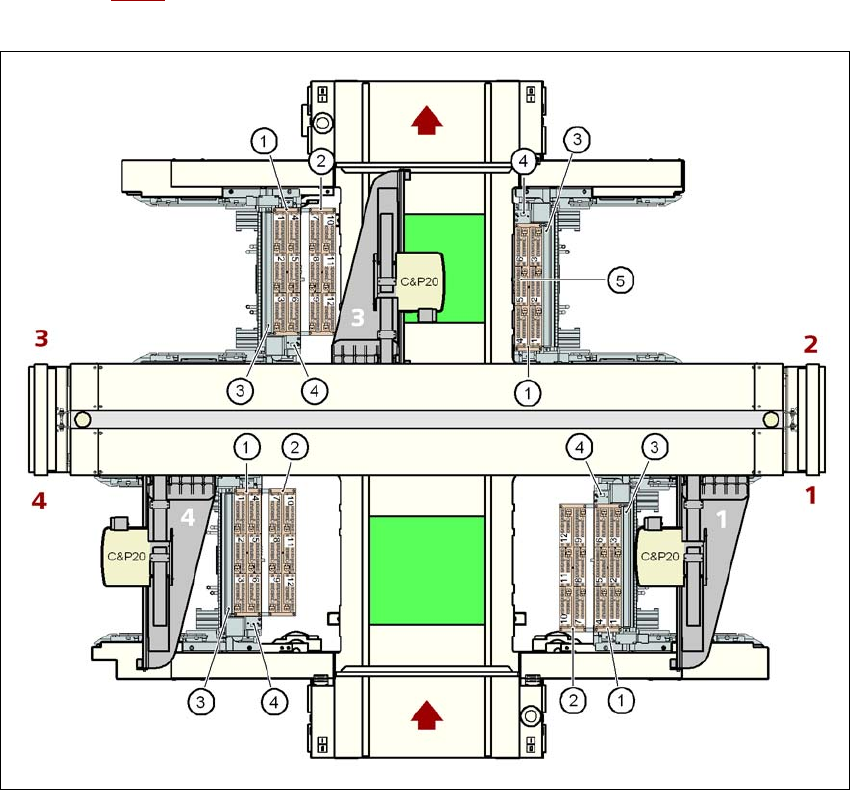
6.1.1.5 Position of the nozzle changers for the SIPLACE SpeedStar on the X3
One or two nozzle changers may be installed at locations 1, 3 and 4 for the SpeedStar (items 1
and 2 in Fig. 6.1 - 4
). One nozzle changer may be installed at location 2. This gives a total capacity
of 7 nozzle changers with 42 magazines and a total of 504 nozzle holders.
6
Fig. 6.1 - 4 Position of the nozzle changers for the SIPLACE SpeedStar on the X3 machine
6
(1) Nozzle changer, "row 1"
(2) Nozzle changer, "row 2"
(3) Reject bin for components
(4) Take-off device and reject bin for nozzles
(5) Nozzle magazine
Station extensions User manual SIPLACE X-series
Nozzle changer From software version SR.70x.xx 01/2011 EN edition
356
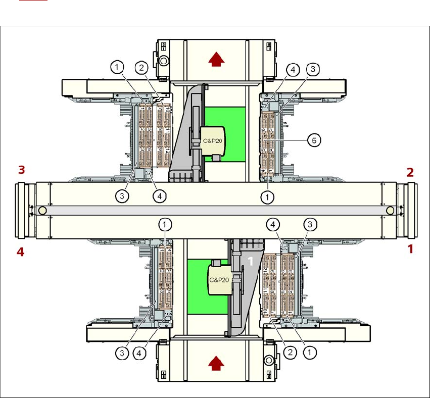
6.1.1.6 Position of the nozzle changers for the SIPLACE SpeedStar on the X2
1 or 2 nozzle changers may be installed at locations 1 and 3 for the SpeedStar (items 1 and 2 in
Fig. 6.1 - 5
). One nozzle changer may be installed at locations 2 and 4. This gives a total capacity
of 6 nozzle changers with 36 magazines and a total of 432 nozzle holders.
6
Fig. 6.1 - 5 Position of the nozzle changers for the SIPLACE SpeedStar on the X2 machine
6
(1) Nozzle changer, "row 1"
(2) Nozzle changer, "row 2"
(3) Reject bin for components
(4) Take-off device and reject bin for nozzles
(5) Nozzle magazine
User manual SIPLACE X-series Station extensions
From software version SR.70x.xx 01/2011 EN edition Nozzle changer
357
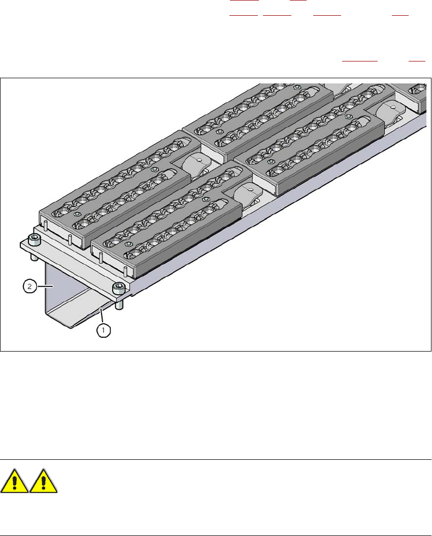
6.1.1.7 Assembly
The nozzle changers for the X4I machine (see Fig. 6.1 - 2, page 353) and the "row 1" nozzle
changers on the X4, X3 and X2 machines (see Fig. 6.1 - 3
, 6.1 - 4 and 6.1 - 5 from page 354) are
each fixed to the component trolley docking unit. A second nozzle changer may be installed on
the SIPLACE X4, X3 and X2 machines. There is an assembly kit for this "row 2" nozzle changer.
This kit consists of the take-off device and the nozzle reject bin (see Section 6.1.1.11
, page 361).
6
Fig. 6.1 - 6 Assembly position
(1) Sloping side points towards the component trolley docking unit
(2) Vertical side points towards the PCB conveyor
→ Align the nozzle changer so that the sloping side points towards the component trolley docking
unit.
WARNING 6
– Only install the associated nozzle changer for each placement head. There is a risk of head
crashes with mixed configurations.