00196504-02_UM_X-Serie_SR70X_EN.pdf - 第406页
Station extensions User manual SIPLACE X-series Component camera for the MultiStar From software version SR.70x.xx 01/2011 EN edition 406 6.7 Component camera for the MultiS tar 6.7.1 S t ationary P&P component cam e…
User manual SIPLACE X-series Station extensions
From software version SR.70x.xx 01/2011 EN edition Component camera for the TwinStar, FC camera
405
6.6.2 Safety instructions
WARNING 6
When the placement head is changed from the TwinStar to the SpeedStar, the TwinStar's station-
ary component cameras (P&P, type 33, 55 x 45, digital, and type 25, 16 x 16, digital (FC camera))
must be removed, otherwise the SpeedStar will collide with the camera housings.
If the placement head is changed from the TwinStar to the MultiStar, the stationary component
camera, type 33, 55 x 45, digital, is installed in the lower position.
6.6.3 Technical data
6
6
6
6
6.6.4 Position
The position of the stationary component cameras and the associated configurations are de-
scribed in Section 3.8.2
, from page 162.
Component dimensions 0.2 x 0.2 mm² up to 16 x 16 mm² for single component measurement
Range of components 0402 to SO, PLCC, QFP, sockets, plugs, BGA, special components,
bare dies, flip-chips, shields
Min. lead pitch 0.25 mm
Min. lead width 0.1 mm
Min. ball pitch 0.14 mm
Min. ball diameter 0.08 mm
Field of vision 19.4 x 19.4 mm²
Method of illumination front-illumination (6 levels, programmable as required)
Station extensions User manual SIPLACE X-series
Component camera for the MultiStar From software version SR.70x.xx 01/2011 EN edition
406
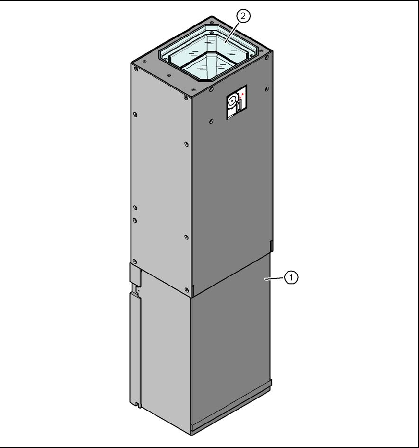
6.7 Component camera for the MultiStar
6.7.1 Stationary P&P component camera, type 33, 55 x 45, digital
Item no. 00119782-xx Stationary camera for the CPP head
6
Fig. 6.7 - 1 Structure for the stationary P&P component camera, type 33, 55 x 45, digital
(1) Camera housing with integral camera and camera amplifier
(2) Glass plate - over the illumination and lens -levels

User manual SIPLACE X-series Station extensions
From software version SR.70x.xx 01/2011 EN edition Component camera for the MultiStar
407
6.7.1.1 Component range
You will find an overview of the components that are centered with the stationary camera in sec-
tion 3.5.2.3
, page 131.
6.7.1.2 Technical data
6
6
6.7.1.3 Position
The position of the stationary component cameras and the associated configurations are de-
scribed in Section 3.8.2
, page 162.
Component dimensions 0.5 x 0.5 mm² to 55 x 45 mm²
Range of components 0402, MELF, SO, PLCC, QFP, electrolytic capacitors, BGA
Min. lead pitch 0.3 mm
Min. lead width 0.15 mm
Min. ball pitch 0.35 mm
Min. ball diameter 0.2 mm
Field of vision 65 x 50 mm²
Method of illumination front-illumination (6 levels, programmable as required)