00196504-02_UM_X-Serie_SR70X_EN.pdf - 第140页
Technical data for the machine User manual SIPLACE X-series Gantry system From software vers ion SR.70x.xx 01/2011 EN edition 140 3.6 Gantry system 3.6.1 Position of the gantries 3.6.1.1 Position of the gantries for the …

User manual SIPLACE X-series Technical data for the machine
From software version SR.70x.xx 01/2011 EN edition Placement head
139
Programmable set-down
force
1.0 N - 15 N
2.0 N - 30 N
d
1.0 N - 15 N
2.0 N - 30 N
d
Nozzle types 5 xx (standard)
4 xx + adapter
8 xx + adapter
9 xx + adapter
gripper
5 xx (standard)
4 xx + adapter
8 xx + adapter
9 xx + adapter
gripper
Nozzle spacing on the two
Pick&Place heads
70.8 mm 70.8 mm
X/Y accuracy
e
± 26 μm / 3, ± 35 μm / 4 ± 22 μm / 3, ± 30 μm / 4
Angular accuracy ± 0.05° / 3, ± 0.07° / 4 ± 0.05° / 3, ± 0.07° / 4
Illumination levels 6 6
Possible illumination level
settings
256
6
256
6
a) Please note that the component range that can be placed is also affected by the pad geometry, the cus-
tomer-specific standards and the packaging tolerances.
b) If the C&P head and the TwinStar are combined in one placement area, the maximum dimensions are
restricted.
c) If standard nozzles are used.
d) SIPLACE High-Force Head, Section 6.5
, page 403.
e) The accuracy value was measured using the vendor-neutral IPC standard.
Technical data for the machine User manual SIPLACE X-series
Gantry system From software version SR.70x.xx 01/2011 EN edition
140
3.6 Gantry system
3.6.1 Position of the gantries
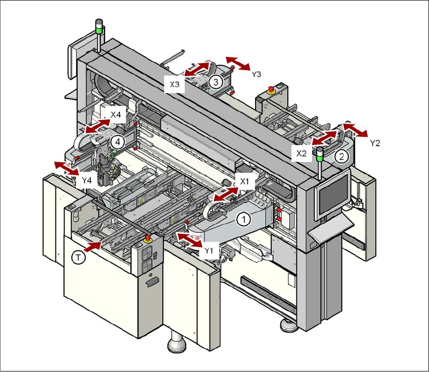
3.6.1.1 Position of the gantries for the X4I machine
3
Fig. 3.6 - 1 Position of the gantries on the X4I machine
a, s, d, f (gantry 1, gantry 2, gantry 3, gantry 4)
X1 X axis, gantry 1
Y1 Y axis, gantry 1
X2 X axis, gantry 2
Y2 Y axis, gantry 2
X3 X axis, gantry 3
Y3 Y axis, gantry 3
X4 X axis, gantry 4
Y4 Y axis, gantry 4
(T) Direction of PCB transport
Placement area 2
Placement area 1
User manual SIPLACE X-series Technical data for the machine
From software version SR.70x.xx 01/2011 EN edition Gantry system
141
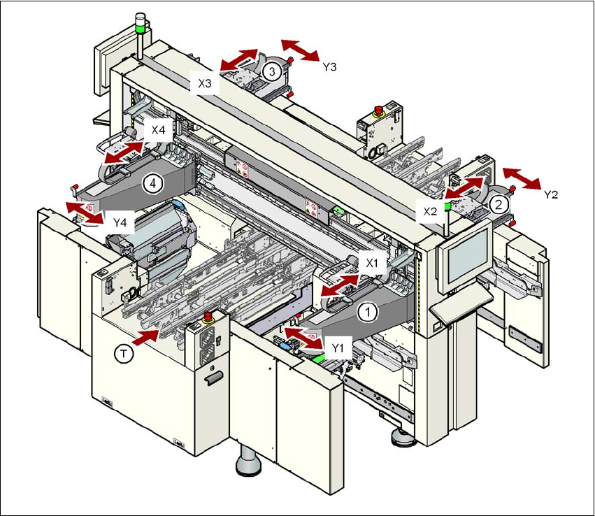
3.6.1.2 Position of the gantries for the X4 machine
3
Fig. 3.6 - 2 Position of the gantries on the X4 machine
a, s, d, f (gantry 1, gantry 2, gantry 3, gantry 4)
X1 X axis, gantry 1
Y1 Y axis, gantry 1
X2 X axis, gantry 2
Y2 Y axis, gantry 2
X3 X axis, gantry 3
Y3 Y axis, gantry 3
X4 X axis, gantry 4
Y4 Y axis, gantry 4
(T) Direction of PCB transport
Placement area 2
Placement area 1