00196504-02_UM_X-Serie_SR70X_EN.pdf - 第257页
User manual SIPLACE X-series Setting up and commissioning From software version SR.70x.xx 01/2011 EN edition Setting up the machine 257 4.3.10.5 Fitting the grounding cable for the doors → Fix the two ground ing cables f…

Setting up and commissioning User manual SIPLACE X-series
Setting up the machine From software version SR.70x.xx 01/2011 EN edition
256
4.3.10.3 Fitting the guide for the hexagonal shaft
→ On the single conveyor, fix one guide for the hexagonal shaft (item 8 in Fig. 4.3 - 14, page
252
) to the extension kit using two fillister head screws M6x16 and washers.
→ On the double conveyor, fix two guides for the hexagonal shaft (item 8 in Fig. 4.3 - 14
, page
252
) to the extension kit using two fillister head screws M6x16 and washers.
4.3.10.4 Producing cable connections - extension kit on the PCB input side
4
Left-hand side of the extension kit
(viewed in the direction of travel)
Connector/cable To connector/
cable
Start/stop button
Switch, PCB conveyor cover
X61/03020410 X61/03002537
Protective cover switch, location 4
X54/03020409 X54/03002540
Button for the component trolley docking unit, loca-
tion 4
X242/03021056 X242/03021054
Right-hand side of the extension kit
(viewed in the direction of travel)
Connector/cable To connector/
cable
EMERGENCY STOP button
Start/stop button
X64/03020687 X64/03002538
Protective cover switch, location 1
X51/03020409 X51/03002539
Button for the component trolley docking unit, loca-
tion 1
X212/03021056 X212/03021051
User manual SIPLACE X-series Setting up and commissioning
From software version SR.70x.xx 01/2011 EN edition Setting up the machine
257
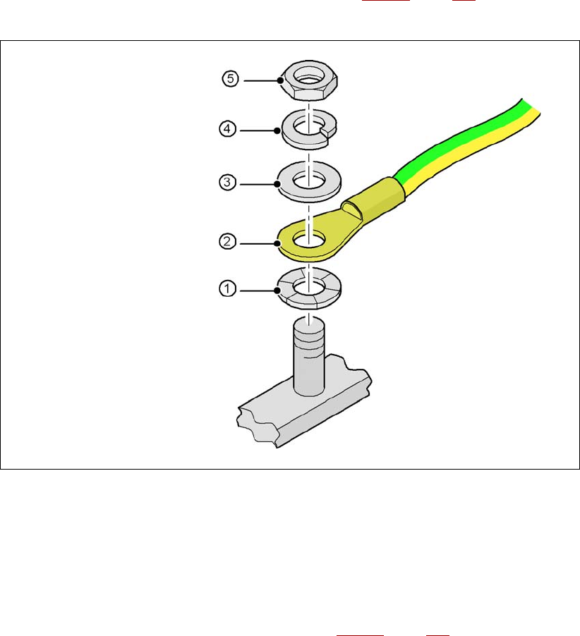
4.3.10.5 Fitting the grounding cable for the doors
→ Fix the two grounding cables for the doors (item 4 in Fig. 4.3 - 15, page 254) to the machine
frame as follows:
4
Fig. 4.3 - 16 Fitting the grounding cable
4
4
4
4
4
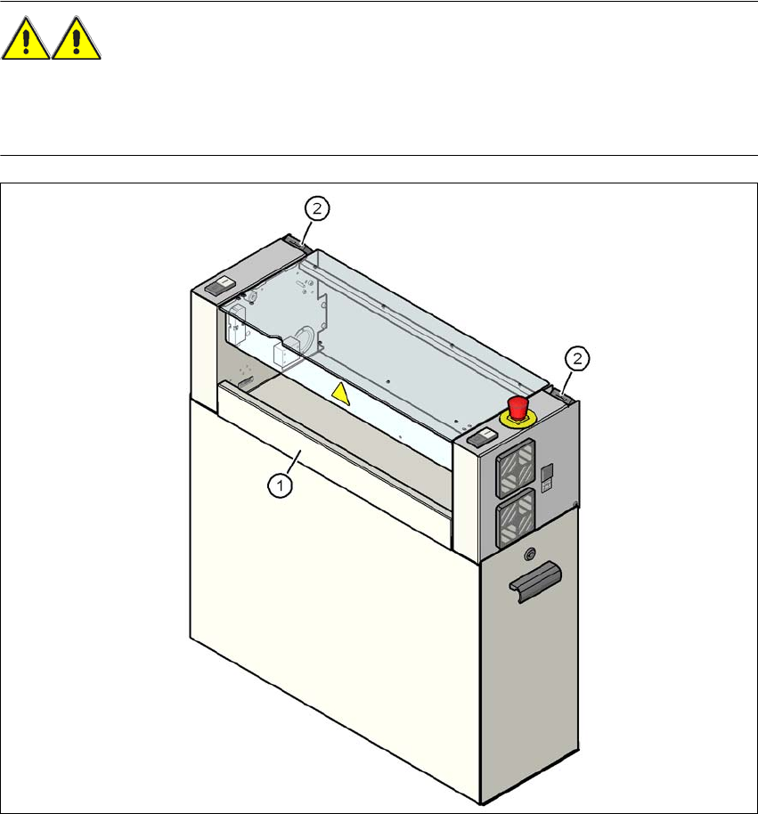
4.3.10.6 Checking and setting the protective cover switch
→ Check that the protective cover switch (item 2 in Fig. 4.3 - 17, page 258) is working correctly.
→ Adjust the protective cover switch if necessary (see service manual).
4
Hex nut M5
Spring washer M5, DIN 7980
Washer M5, DIN 125
Cable lug, annular
Contact washer
Setting up and commissioning User manual SIPLACE X-series
Setting up the machine From software version SR.70x.xx 01/2011 EN edition
258
4.3.10.7 Fitting the "bottom" hand guard
The machines are supplied with just one "bottom" hand guard. If the machines are installed within
a line, then no hand guard is required between immediately adjacent output and input conveyors.
WARNING 4
Always fit the "bottom" hand guard (item no. 03045426-01) on the input side of the first machine
and on the output side of the last machine of a line using 4 hexagon socket head screws M4x12.
This will prevent your personnel reaching into the machine without authorization.
4
Fig. 4.3 - 17 Fitting the "bottom" hand guard on the PCB output side
(1) "Bottom" hand guard, item no. 03045426-xx
(2) Protective cover switch