00196504-02_UM_X-Serie_SR70X_EN.pdf - 第329页
User manual SIPLACE X-series Tasks on the machine From software version SR.70x.xx 01/2011 EN edition Setting up the feeder modules 329 → Close the pick-up window (ite m 3 in Fig. 5.10 - 2 ) by returning the lever (item 4…

Tasks on the machine User manual SIPLACE X-series
Setting up the feeder modules From software version SR.70x.xx 01/2011 EN edition
328
The X feeder module is locked in position in the component table by a latch, and cannot be pulled
out. The procedure for removing feeder modules from the component table is as follows:
→ Press the removal handle (item 1 in Fig. 5.10 - 1
, page 327). The removal handle jumps
out and the status display goes out.
→ Wait approximately 1 second until the lock (item 4 in Fig. 5.10 - 1
, page 327) releases
the feeder module.
→ Use the removal handle to pull the feeder module out of the component table. If you wait
longer than 5 seconds, the feeder module will be locked once more. The status display
lights up red and the message "Handle --->>" appears on the LCD display (item 3 in Fig.
5.10 - 1
, page 327).
→ Engage the removal handle once more. If the X feeder module is contained in the current
set-up, the status display lights up green and the track number and increment are appear
on the LCD display once more.
→ Press the removal handle again (item 1 in Fig. 5.10 - 1
, page 327) and now pull the feeder
module out of the component table.
5.10.3 Using the X feeder module on the component trolley
5.10.3.1 Check the X feeder module before using it
Check the following points before you use a feeder module on the component table:
→ The feeder module must be in perfect condition.
→ Tap the cover foil rocker (item 2 in Fig. 5.10 - 2
, page 329) lightly to make sure that it is
not jammed.
→ Check that the area around the pick-up window (item 3 in Fig. 5.10 - 2
, page 329) is free
from loose components.
PLEASE NOTE 5
Empty the component disposal compartment (item 5 in Fig.5.10 - 2
, page 329) before you
shake components out of the feeder module.
→ Push the lever (item 4 in Fig. 5.10 - 2
, page 329) forward slightly to open the pick-up win-
dow (item 3 in Fig. 5.10 - 2
, page 329). This will raise the pick-up window slightly.
PLEASE NOTE 5
Do not press the lever if a component tape is inserted. The tensioned cover foil would move
the component tape on and expose the components.
→ Remove any loose components from beneath the pick-up window.
User manual SIPLACE X-series Tasks on the machine
From software version SR.70x.xx 01/2011 EN edition Setting up the feeder modules
329
→ Close the pick-up window (item 3 in Fig. 5.10 - 2) by returning the lever (item 4 in Fig.
5.10 - 2
) to its original position.
→ Remove loose components from the component table with a brush or use a vacuum
cleaner with appropriate nozzle.
PLEASE NOTE 5
If the component tape is already inserted, cut it off flush with the front edge of the feeder mod-
ule.
→ If the removal handle (item 1) is still protruding, then latch it in place.
5
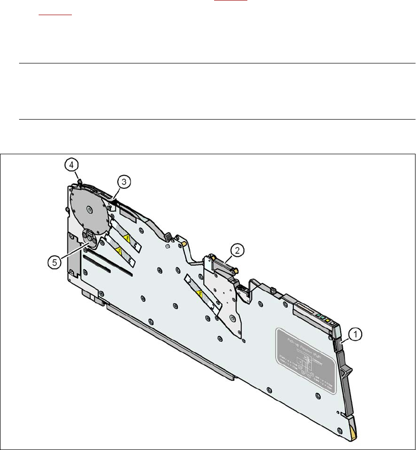
Fig. 5.10 - 2 Check the X feeder module before using it
(1) Removal handle
(2) Cover foil rocker
(3) Pick-up window
(4) Lever for raising and latching the pick-up window
(5) Component disposal compartment
Tasks on the machine User manual SIPLACE X-series
Setting up the feeder modules From software version SR.70x.xx 01/2011 EN edition
330
5.10.3.2 Inserting the X feeder module into the component table
5
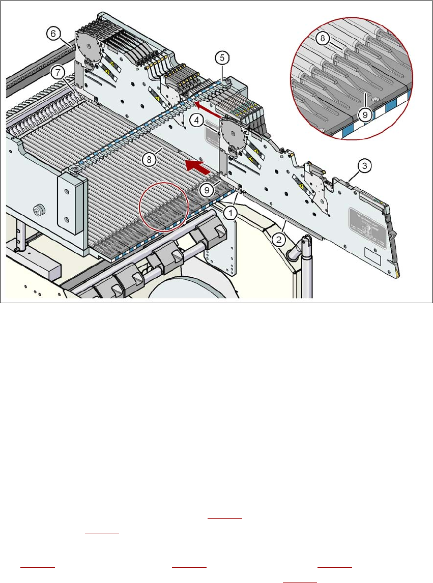
Fig. 5.10 - 3 Inserting the X feeder module into the component table
(1) Front slider guide for the X feeder module
(2) Back slider guide for the X feeder module
(3) "Back" centering pin on the X feeder module
(4) "Front" centering pin on the X feeder module
(5) Recesses in the centering bar for holding the "back" centering pin
(6) Centering holes on the component table for holding the "front" centering pin
(7) Locking latches
(8) Guide profile for the component table ( profile)
(9) Insertion aid for the feeder module
5
→ Place the front slider guide (item 1 in Fig. 5.10 - 3) of the feeder module on the insertion aid
(item 9 in Fig. 5.10 - 3
) of the component table.
→ Hold the feeder module vertically and push it forward, along the guide profile (item 8 in Fig.
5.10 - 3
). The front (item 1 in Fig. 5.10 - 3) and rear (item 2 in Fig. 5.10 - 3) slider guides of
the feeder module slide on the guide profile (item 8 in Fig. 5.10 - 3
).