00196504-02_UM_X-Serie_SR70X_EN.pdf - 第404页
Station extensions User manual SIPLACE X-series Component camera for the TwinStar, FC camera From software version SR.70x.xx 01/2011 EN edition 404 6.6 Component camera for the T winS t ar , FC camera 6.6.1 S t ationary …

User manual SIPLACE X-series Station extensions
From software version SR.70x.xx 01/2011 EN edition Sensor for the component reject bin
403
6.4 Sensor for the component reject bin
Item no. 00116848-xx Sensor, component reject bin, X-series/D3
The sensor for the component reject bin monitors whether the reject bin is seated correctly in its
mount.
– If the reject bin was not inserted correctly, the machine cannot be started.
– If the reject bin jumps out of its mount during the placement process, the machine is stopped
immediately to avoid a head crash.
Each reject bin can be monitored by a separate sensor.
PLEASE NOTE 6
If a SpeedStar is used, then we recommend that you install the optional sensor for the compo-
nent reject bin.
6.5 SIPLACE high-force head
Item no. 00119734-xx High-force head for the X-series
This item number only applies when a new placement machines is ordered with a high-force
head rather than a standard TwinStar. 6
Item no. 00119753-xx High-force head upgrade kit
Use this item number if you want to replace a standard TwinStar with a high-force head. 6
6.5.1 Description
The SIPLACE high-force head is a development offshoot of the standard TwinStar. It can process
the same component range and also offers the possibility of achieving set-down forces up to 30 N.
6.5.2 Technical data
6
Otherwise the technical data for the TwinStar and high-force head is the same (see Section
3.5.3.2
, page 138).
All the nozzles and grippers that are used with the standard TwinStar can be used for the
SIPLACE high-force head.
Programmable set-down force 2.0 N to 10 N ± 10 %
greater than 10 N up to 30 N ± 15 %
Station extensions User manual SIPLACE X-series
Component camera for the TwinStar, FC camera From software version SR.70x.xx 01/2011 EN edition
404
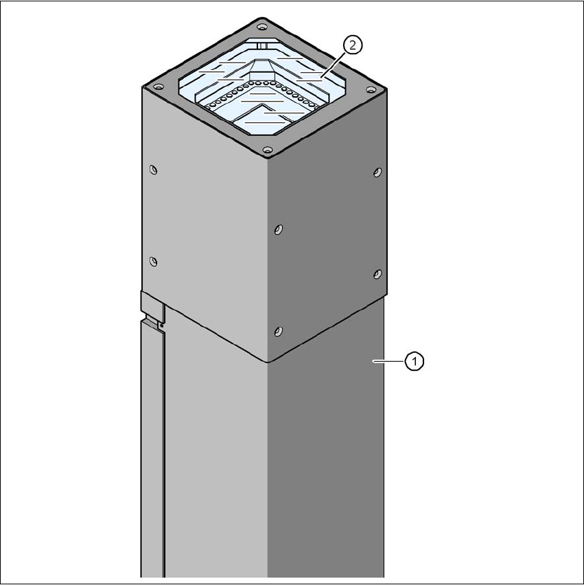
6.6 Component camera for the TwinStar, FC camera
6.6.1 Stationary P&P component camera (type 25) 16 x 16, digital (FC camera)
Item no. 00119718-xx Component camera, stationary, 16x16, digital, type 25
6
Fig. 6.6 - 1 Stationary P&P component camera (type 25) 16 x 16, digital (FC camera)
(1) Camera housing with integral camera and camera amplifier
(2) Glass plate - over the illumination and lens -levels
User manual SIPLACE X-series Station extensions
From software version SR.70x.xx 01/2011 EN edition Component camera for the TwinStar, FC camera
405
6.6.2 Safety instructions
WARNING 6
When the placement head is changed from the TwinStar to the SpeedStar, the TwinStar's station-
ary component cameras (P&P, type 33, 55 x 45, digital, and type 25, 16 x 16, digital (FC camera))
must be removed, otherwise the SpeedStar will collide with the camera housings.
If the placement head is changed from the TwinStar to the MultiStar, the stationary component
camera, type 33, 55 x 45, digital, is installed in the lower position.
6.6.3 Technical data
6
6
6
6
6.6.4 Position
The position of the stationary component cameras and the associated configurations are de-
scribed in Section 3.8.2
, from page 162.
Component dimensions 0.2 x 0.2 mm² up to 16 x 16 mm² for single component measurement
Range of components 0402 to SO, PLCC, QFP, sockets, plugs, BGA, special components,
bare dies, flip-chips, shields
Min. lead pitch 0.25 mm
Min. lead width 0.1 mm
Min. ball pitch 0.14 mm
Min. ball diameter 0.08 mm
Field of vision 19.4 x 19.4 mm²
Method of illumination front-illumination (6 levels, programmable as required)