00196504-02_UM_X-Serie_SR70X_EN.pdf - 第315页
User manual SIPLACE X-series Tasks on the machine From software version SR.70x.xx 01/2011 EN edition Indicato r lamp status displays 315 5.7 Indicator lamp st atus displays The indicator lamp s are used to signal operati…

Tasks on the machine User manual SIPLACE X-series
Alarm information and online help From software version SR.70x.xx 01/2011 EN edition
314
Click the "Show help" button (4) to display the information.
You can search for and display alarm information about another alarm via the help system -index
(5) by entering the alarm number.
5.6.3 Meaning of the colors in the alarm information in the online help
5
5.6.4 Context-sensitive online help
To display information about the current view, click the symbol to start the help system for
the station computer. The main help system window opens with the -alarm information. This in-
formation relates to the currently-displayed view from which the help was started. You can call up
the entire content of the online help using the contents, index and search functions.
Text marking Meaning
Red text Alarm number and alarm message
Black text Possible cause(s) of the alarm
Green text Instructions to eliminate the alarm
Blue underlined text Calls up additional information
User manual SIPLACE X-series Tasks on the machine
From software version SR.70x.xx 01/2011 EN edition Indicator lamp status displays
315
5.7 Indicator lamp status displays
The indicator lamps are used to signal operating statuses and malfunctions of the placement ma-
chine.
5.7.1 Description of the functions
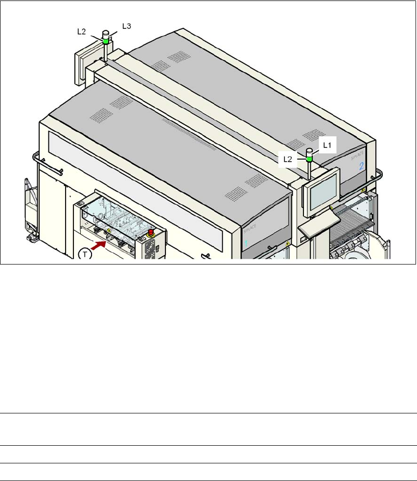
Fig. 5.7 - 1 Operating status indicator lamps
L1 White indicator lamp, right
L2 Green indicator lamp, both lamps switched in parallel
L3 White indicator lamp, left
T Direction of PCB transport
5
5
5.7.2 Flashing frequencies
5
Normal flashing Green indicator lamp: 700 ms off, 700 ms on
White indicator lamp: 500 ms off, 500 ms on
Brief flashing 100 ms on, 1000 ms off
Rapid flashing 100 ms on, 200 ms off

Tasks on the machine User manual SIPLACE X-series
Indicator lamp status displays From software version SR.70x.xx 01/2011 EN edition
316
5.7.3 Green indicator lamps
There is one green lamp on each side. They are connected in parallel so that they are always syn-
chronized. The green lamp signals that the machine is in production mode or has been paused.
PLEASE NOTE 5
A combination of green and white lamps is used during a reference run, a manual function or a
calibration process - see section 5.7.5, page 320.
Status Meaning
Off The machine was paused (by the operator or by an alarm)
Normal flashing The machine is running in production mode, but is not currently
producing for one or both of the following reasons:
– Waiting for PCB in the input area.
– And/or waiting for the output area to become free
("conveyor jam" or waiting for a PCB to be removed)
Brief flashing The machine was paused
and
The machine is currently unable to produce: something still has to
be done, such as:
– Waiting for job and set-up data
– A reference run - a part of it (such as feeder module position
detection, or checking the nozzle configuration) is still pend-
ing.
– The axes must be moved before production starts.
On The machine is producing, even though a warning was output.