00196504-02_UM_X-Serie_SR70X_EN.pdf - 第416页
Station extensions User manual SIPLACE X-series PCB barcode scanner From software version SR.70x.xx 01/2011 EN edition 416 6.10 PCB barcode scanner Item no. 00519881-xx PCB barcode scann er , 2D, X/SX machine Item no. 00…
User manual SIPLACE X-series Station extensions
From software version SR.70x.xx 01/2011 EN edition 3D coplanarity sensor
415
6
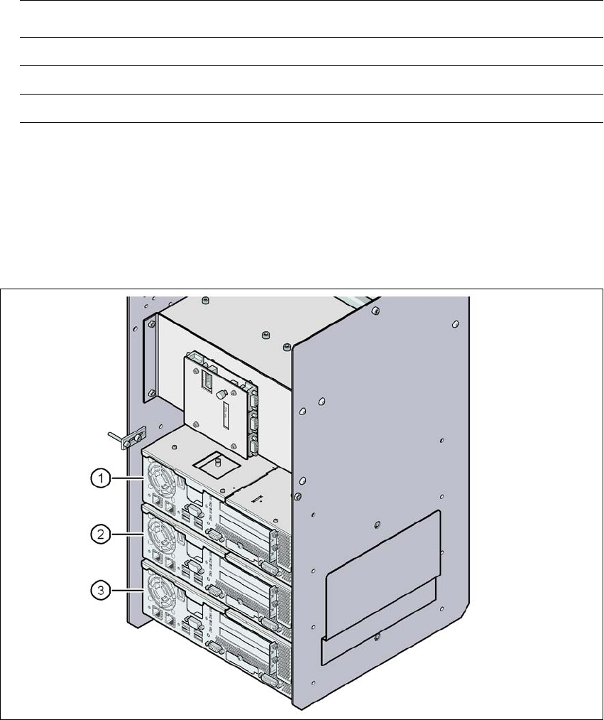
6.9.7 Analysis computer
A box PC acts as an analysis computer. It is housed together with the control computer and the
machine controller on the input side.
6
Fig. 6.9 - 4 Box PC for the 3D coplanarity sensor
(1) Control computer
(2) Machine controller
(3) Analysis computer for the 3D coplanarity sensor
Placement machine Location
SIPLACE X2 3
SIPLACE X3 3
SIPLACE X4 2 or 3

Station extensions User manual SIPLACE X-series
PCB barcode scanner From software version SR.70x.xx 01/2011 EN edition
416
6.10 PCB barcode scanner
Item no. 00519881-xx PCB barcode scanner, 2D, X/SX machine
Item no. 00176112-xx Mount for Data Man X/HS/HF top
Item no. 00176113-xx Mount for Data Man X/HS/HF bottom
item no. 00176118-xx Cognex I/O module
Item no. 00176119-xx Cognex USB cable DM 100 USB 000
Item no. 00176120-xx Cable for I/O box interface
6.10.1 Description
The PCB barcode scanner is used to automatically record and decode barcodes on PCBs. As the
component density on PCBs constantly increases, the space available for barcodes is becoming
increasingly smaller. We have therefore developed new PCB barcode scanners for the SIPLACE
X-series that guarantee reliable processing of even these reduced barcodes. The barcode scan-
ner can process 2D matrix codes and 1D barcode.
The PCB barcode scanners are installed on the input side of the placement machine on the PCB
conveyor. Up to four devices can be retrofitted to each machine. The barcode scanners are fitted
so that the barcode labels on the topside and underside of the PCBs can be scanned on both
tracks of the dual conveyor.
The PCB barcode scanners are fixed to the top and bottom profiled rail using retainers. These can
be positioned as required on the profiled rails, and aligned with respect to the barcode labels. De-
pending on the position of the barcode strips, the -barcode scanner can be attached in a few sim-
ple steps so that the strips can be read parallel to or across the PCB transport direction.
6.10.2 Technical data
6
Sensor 1/3 CMOS (resolution 752 x 480)
Frame rate max. 60 fps
Optical signaling 1 read LED
1 communication LED
Acoustic signaling programmable buzzer
Data interface RS232, USB 2.0
Operating voltage 5 VDC ... 24 VDC
Power consumption max. 2.5 W
Electrical connection 15-pin D-Sub HD connector
Dimensions 55 x 42 x 22 mm³
Weight 125 g

User manual SIPLACE X-series Station extensions
From software version SR.70x.xx 01/2011 EN edition PCB barcode scanner
417
1D code types UPC, EAN, Codabar 2/5 Interleaved, Code 39, Code
128, Code 99
2D code types Data Matrix ECC 200