00196504-02_UM_X-Serie_SR70X_EN.pdf - 第393页
User manual SIPLACE X-series Station extensions From software version SR.70x.xx 01/2011 EN edition Dock ing station for the SIPLACE X-series CO tr olley 393 → Hold the component trolley docki ng unit firmly by the FCU (i…
Station extensions User manual SIPLACE X-series
Docking station for the SIPLACE X-series CO trolley From software version SR.70x.xx 01/2011 EN edition
392
PLEASE NOTE 6
Reverse the sequence to convert from a height of 900 mm to 830 mm (see Fig. 6.2 - 6
, page
390).
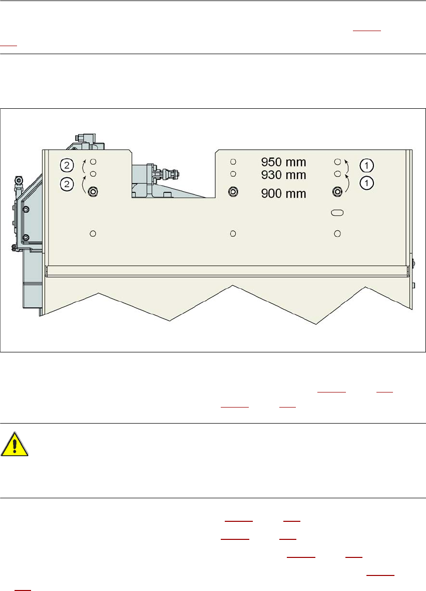
6.2.5.4 Converting the CO trolley docking unit to a height of 900, 930 or 950 mm
6
Fig. 6.2 - 7 Steps for conversion from a height of 830 mm to a height of 900 mm
→ Remove the two hexagon socket head screws M8x18 (item 9 in Fig. 6.2 - 5, page 389) and
remove the left and right guides (item 8 in Fig. 6.2 - 5
, page 389).
CAUTION 6
Be careful not to damage any cables while raising and lowering the component trolley docking
unit.
→ Release both screw connections (item 3 in Fig. 6.2 - 5, page 389).
→ Loosen both screw connections (item 2 in Fig. 6.2 - 5
, page 389).
→ Remove both M8 hexagonal nuts and washers (item 4 in Fig. 6.2 - 5
, page 389).
→ Hold the component trolley docking unit firmly by the side panel (item 10 in Fig. 6.2 - 5
, page
389
) while you remove the two hexagon socket head screws M8x40 at this point.
→ Swivel the component trolley docking unit to the next highest position.
→ Fasten the side section at this location. Only hand-tighten the nuts.
User manual SIPLACE X-series Station extensions
From software version SR.70x.xx 01/2011 EN edition Docking station for the SIPLACE X-series CO trolley
393
→ Hold the component trolley docking unit firmly by the FCU (item 12 in Fig. 6.2 - 5, page 389)
while you remove the screwed connections at item 2 in Fig. 6.2 - 5
, page 389.
→ Swivel the component trolley docking unit into the next highest position.
→ Fasten the side section at this location.
→ Check all screw connections at items 2, 3 and 4 for form seating.
→ Fix the left and right guides (item 8 in Fig. 6.2 - 5
, page 389) using the hexagon socket head
screw M8x18 (item 9 in Fig. 6.2 - 5
, page 389).
PLEASE NOTE 6
Reverse the sequence (see Fig. 6.2 - 6
, page 390) if the component trolley docking unit should
be brought down to a lower transport height.
Station extensions User manual SIPLACE X-series
Matrix tray changer From software version SR.70x.xx 01/2011 EN edition
394
6.3 Matrix tray changer
Item no. 00116438-xx SIPLACE matrix tray changer (MTC)
6.3.1 Safety instructions
WARNING 6
→ Never reach into the gaps between the matrix tray changer and the machine base while the
machine is running.
→ The power supply cable must not be plugged into or unplugged from the external power supply
unless the matrix tray changer is docked into the machine.
→ The matrix tray changer must NOT be operated unless it is docked into the machine.
6.3.2 Description
The matrix tray changer can be used to store and change up to 100 waffle-pack trays fully auto-
matically. The levels (storage locations in the tray supplies) for the waffle-pack trays are numbered
consecutively in ascending order from bottom to top.
The tray supplies move independently of one another in the vertical direction until the selected
magazine is within range of the feed axis. The horizontal feed axis transports the waffle-pack tray
from the tray supply into the access area of the placement head.
Tray supply 1 has 30 levels, each of which can hold 2 JEDEC trays or one large tray up to 240 x
340 mm² from the waffle-pack tray carriers.
Tray supply 2 has a capacity of 40 levels for JEDEC trays.
The matrix tray changer has an integral chassis, and is therefore easy to move to other locations.
It is supplied with the PCB conveyor height implemented for the machines, but can be adapted for
the 830, 900, 930 and 950 mm PCB conveyor heights with just a few simple operations.